2010:Mechanical 2 01.12: Difference between revisions
From 1511Wookiee
Jump to navigationJump to search
Mechanical2 (talk | contribs) No edit summary |
Mechanical1 (talk | contribs) No edit summary |
||
| (21 intermediate revisions by 2 users not shown) | |||
| Line 5: | Line 5: | ||
End time: 9:15 PM | End time: 9:15 PM | ||
Members present: Alex W.,Nathan K.,Mike Mo.,Jake K.,Mike Mac.,Chris H., Kristina K., Shauna R., Becca H., Sam _., Alex V., Tom C., Dave V., Mike W. | |||
---- | ---- | ||
| Line 13: | Line 13: | ||
*We worked together to come up with a mechanism design. | *We worked together to come up with a mechanism design. | ||
*We jointly worked with drivetrain to review constraints and other important details | *We jointly worked with drivetrain to review constraints and other important details | ||
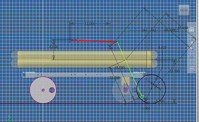
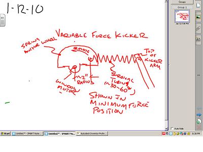
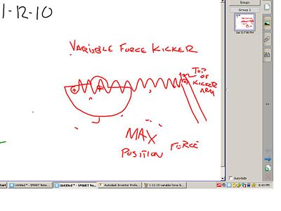
*We started working with a "golf club shooter" by manipulating designs on | *We started working with a "golf club shooter" by manipulating designs on Inventor | ||
*We did not finish working on a final design and but did calculate the force needed to hit the ball effectivly 30 feet at 10 | *We did not finish working on a final design and but did calculate the force needed to hit the ball effectivly 30 feet at 10 m/second... It was calculated that this would required approximately 32 lbs of force applied to the ball for 6 inches of the contact with the ball. | ||
*Tomorrow we should continue working with designs and with cad to refine a possible mechanism design. | *Tomorrow we should continue working with designs and with cad to refine a possible mechanism design. | ||
*< | *Brief experiment was performed to understand force capability of the surgical tubing supplied in the KOP. 8 strains approximately 12" long exert a force of approximately 43 pounds when streched to approximately 19". | ||
*<span style="color: rgb(255,0,0)">'''The images from today are in the wiki and have been inserted in the Images & Additional information section directly below. '''</span><br> | |||
---- | ---- | ||
| Line 40: | Line 41: | ||
(Use the upload file button on the toolbox to the left to upload the file, then insert an image using the button above. Sizing can be done using the length/width pixel size) <br> | (Use the upload file button on the toolbox to the left to upload the file, then insert an image using the button above. Sizing can be done using the length/width pixel size) <br> | ||
[[Image:1-12-10 | <br>[[Image:1-12-10 kicker drawing.jpg|thumb|left|400px|Spatial View Inventor]] | ||
[[Image:Variable Force Ball Kicker - Retracted 2.jpg|thumb|left|400px|Variable Force Ball Kicker - Retracted]] | |||
[[Image:1-12-10 variable force kicker max position.JPG|thumb|left|400px|Variable Force Tubing Anchor - Max Position]] | [[Image:Variable Force Ball Kicker - Fully Extended after Firing.jpg|thumb|right|400px|Variable Force Ball Kicker - Fully Extended after Firing]] | ||
[[Image:Over Running Clutch Actuator - Full Size.jpg|thumb|left|400px|Over Running Clutch Actuator - Full Size]] | |||
<u>How It works[[Image:1-12-10 variable forcer kicker min position.JPG|thumb|left|400px|Variable Force Tubing Anchor - Min Position]]</u> | |||
*Link A is connected to the Kicker and Link B with a pin. | |||
*Link B is free to rotate independent of the Drive Dog Pulley. | |||
*Drive Dog pulley has a bronze bushing sleeve in it for the Link B shaft to rotate freely indepentent of the pulley. | |||
*The Drive Dog pulley is solid aluminum with the Drive Dog key screwed to it. | |||
* The Drive Dog pulley is driven by a motor clockwise. | |||
*As the Driver Dog pulley rotated clockwise the Drive Dog hits the side of Link B also causing it to rotate clock wise. | |||
*When the Link A-to-B pin is below the horizontal centerline of [[Image:1-12-10 variable force kicker max position.JPG|thumb|left|400px|Variable Force Tubing Anchor - Max Position]]the Drive Dog pulley it pulls the kicker arm back to the retracted position at the same time increasing the tension in the surgical tubing spring and stops at a position prior to Link A's center axis of the Drive Dog Pulley. | |||
*<u>To Fire </u>- The driver presses the fire button and the Drive Dog motor starts to rotate clockwise again with the drive dog pulley also rotating Link B. | |||
*When the centerline of Link A passes by the center access of the Drive Dog Pulley the stored spring force is instantaneously released as Link B is free to "overrun" forward independent from the Drive Dog and the kicker are surges to kick the ball. | |||
*[[Image:1-12-10 kicker drawing.jpg]] | |||
Latest revision as of 17:03, 13 January 2010
01.12.2010
Start time: 6:45 PM
End time: 9:15 PM
Members present: Alex W.,Nathan K.,Mike Mo.,Jake K.,Mike Mac.,Chris H., Kristina K., Shauna R., Becca H., Sam _., Alex V., Tom C., Dave V., Mike W.
Tasks Completed:
- We worked together to come up with a mechanism design.
- We jointly worked with drivetrain to review constraints and other important details
- We started working with a "golf club shooter" by manipulating designs on Inventor
- We did not finish working on a final design and but did calculate the force needed to hit the ball effectivly 30 feet at 10 m/second... It was calculated that this would required approximately 32 lbs of force applied to the ball for 6 inches of the contact with the ball.
- Tomorrow we should continue working with designs and with cad to refine a possible mechanism design.
- Brief experiment was performed to understand force capability of the surgical tubing supplied in the KOP. 8 strains approximately 12" long exert a force of approximately 43 pounds when streched to approximately 19".
- The images from today are in the wiki and have been inserted in the Images & Additional information section directly below.
Tasks In Progress:
- task
* task
Tasks to Complete:
- task
* task
Images & Additional Updates:
(Use the upload file button on the toolbox to the left to upload the file, then insert an image using the button above. Sizing can be done using the length/width pixel size)
How It works
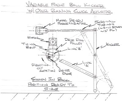
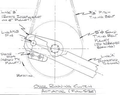
- Link A is connected to the Kicker and Link B with a pin.
- Link B is free to rotate independent of the Drive Dog Pulley.
- Drive Dog pulley has a bronze bushing sleeve in it for the Link B shaft to rotate freely indepentent of the pulley.
- The Drive Dog pulley is solid aluminum with the Drive Dog key screwed to it.
- The Drive Dog pulley is driven by a motor clockwise.
- As the Driver Dog pulley rotated clockwise the Drive Dog hits the side of Link B also causing it to rotate clock wise.
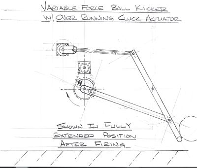
- When the Link A-to-B pin is below the horizontal centerline of the Drive Dog pulley it pulls the kicker arm back to the retracted position at the same time increasing the tension in the surgical tubing spring and stops at a position prior to Link A's center axis of the Drive Dog Pulley.
- To Fire - The driver presses the fire button and the Drive Dog motor starts to rotate clockwise again with the drive dog pulley also rotating Link B.
- When the centerline of Link A passes by the center access of the Drive Dog Pulley the stored spring force is instantaneously released as Link B is free to "overrun" forward independent from the Drive Dog and the kicker are surges to kick the ball.

