2018:Cube Mechanism: Difference between revisions
From 1511Wookiee
Jump to navigationJump to search
No edit summary |
Mechanical1 (talk | contribs) No edit summary |
||
| (13 intermediate revisions by 2 users not shown) | |||
| Line 1: | Line 1: | ||
= '''<u>Cube Subteam</u>''' = | = '''<u>Cube Subteam</u>''' = | ||
'''Leads:''' Tom C, Andrew F, Matt D | |||
<div class="mw-parser-output"> | |||
<div class="mw-parser-output"> | |||
== Current Intake == | == Current Intake == | ||
*Weight: 6.292 lb + fasteners | *Weight: 6.292 lb + fasteners | ||
* | *2 775pros geared with 5:1 and 3:1 for 15:1 reduction | ||
* | *'''''Things we need to document here''''': | ||
** | **How is this held inside frame perimeter? With the 3/4" bore x4.0" stroke air cylinder extended, it puts pressure on a level that holds the assembly vertical or past vertical leaning into the robot. | ||
** | **What kind of action or actuations make it "deploy" outward? When should this happen? Is it retractable after deployed? Retraction of the air cylinder will cause the intake subassembly to rotate CCW (facing the left side of the robot) 90 degrees to the fully deployed position. There is a hard stop. Actuaction should happen prior to intaking a cube. It is thought that the intake will remain retracted (for protection, until needed to intake a cube. Yes it is retractable after deployment.. | ||
** | **What is the intended operation of the 2 775's? Run always? Run until cube in place? Driver on/off manually? They run in opposite directions: Cube in, left motor runs CW, right one runs CCW. To expell a cube, left runs CCW, right runs CW. Driver should have control to start the intake. Cube in position at front frame rail or at arm roller pick up, the intake rollers should stop. | ||
**Is there any articulation parallel to the ground? What controls that? It may be desirable to have the arms float, so that if hit from the front, the arms could move upward. At best the thought would be to remove air from the cylinder (both ports to vent). The intake rollers (4 in dia. wheels) will float on the hex drive shaft as well. One possible control option would be to give drivers a button the intakes while held down, and expells while another button is held down.. | |||
** | |||
[[File:1- | [[File:Intake 1-25-2018.PNG|RTENOTITLE]] </div> | ||
</div> | |||
== Current Cube Transport == | |||
* We have decided on an arm design. | |||
* The plan is to be able to rotate 180+ degrees for easy Power Cube Zone to Exchange times. | |||
* '''''Things we need to document here''''': | |||
** What actually moves on this thing? Only the pivot of the "shoulder" of the arm is obvious from the drawings. Rollers? Wheels? Top? Bottom? Both? | |||
** What is the actual overall travel? (number of degrees total travel, from what angle with ground/frame to what angle?) | |||
** What does the "U" on the end of the arm look like? Concept drawing? CAD? Anything? | |||
** How does the hand-off from the intake to this work? (what angle to go to? what does intake need to do to be compatible with the hand off? what parts on this need to move in what way?) | |||
** What is the intended operation to "score" on the switch? (what angle to go to? what needs to move?) | |||
** What is the intended way to pass through to exchange? (what angle to go to? what needs to move?) | |||
** How does the arm maintain a stable angular position? Will it backdrive? | |||
** How does this thing know what it's angular position is? How can it be controlled? | |||
** How does the cube-holding work? what keeps it in place? | |||
** What is starting position? | |||
** What is most stable position for high speed driving? Does this change with/without a cube? | |||
<span style="font-size:small;">Calculations have been done for the arm and the next task will be to figure out gearing and sprocket sizes to finalize the numbers. </span> | |||
<span style="font-size:small;">[[File:Rotating Arm Geometry Picture.PNG|RTENOTITLE]]</span> | |||
=== Stress Analysis === | |||
<span style="font-size:small;">[[File:Safty.PNG]]</span> | <span style="font-size:small;">[[File:Safty.PNG]]</span> | ||
<span style="font-size:small;">[[File:Displacement analysis 13.PNG]]</span> | <span style="font-size:small;">[[File:Displacement analysis 13.PNG]]</span> | ||
= Meeting Notes = | |||
1/7 - Sunday: | 1/7 - Sunday: | ||
| Line 89: | Line 103: | ||
*Intake | *Intake | ||
**Estimated weight: 6.292 lb (not including fasteners) | **Estimated weight: 6.292 lb (not including fasteners) | ||
**Put parts on shopping list: | |||
***Motors and gearboxes | |||
***Bearings/Bushings | |||
***Aluminum stock | |||
= Historical Design Documentation = | |||
== Intake == | |||
=== Prototype Intake === | |||
*Side rollers with 1 blue compliance wheel on each side as close to the ground as possible. | |||
*Rollers are on arms that can pivot outwards and are tensioned with surgical tubing attached to the frame. | |||
*Rollers are belted to motors mounted on the arms. | |||
**2 775pros geared 30:1. | |||
**Changed to MiniCIMs geared 8:1. | |||
*10.5" long arms. | |||
*Intake must grab the cube in a way that when it flips over to the other side the cube is in the right position for the exchange. | |||
*Capable of grabbing any cube it touches. | |||
[[File:1-14-18 Intake Packaging .jpg|800px|1-14-18 Intake Packaging .jpg]] | |||
This drawing depicts how the intake would fold into the drive train. | |||
*Note: this design is not being used, the intake now pivots up instead. | |||
== Transport == | |||
=== Time Trials === | |||
On 1/10/2018 time trials were conducted using past years' robots to determine how much driver control affected timings for picking up a CUBE and getting it to the EXCHANGE. Picking up, driving backwards and delivering the CUBE to the EXCHANGE was compared to picking up a CUBE, turning 180 degrees, abd delivering the CUBE to the EXCHANGE. | |||
{| border="1" cellspacing="1" cellpadding="1" style="width: 470px;" | |||
|- | |||
| style="width: 142px;" | | |||
| style="width: 59px;" | 2016 | |||
| style="width: 56px;" | 2017 | |||
| style="width: 74px;" | AVERAGE | |||
| style="width: 117px;" | 16" FP Extensions | |||
|- | |||
| style="width: 142px;" | 180 Degree Turn | |||
| style="width: 59px;" | 53 | |||
| style="width: 56px;" | 47 | |||
| style="width: 74px;" | 50 | |||
| style="width: 117px;" | 42 | |||
|- | |||
| style="width: 142px;" | Back & Forth | |||
| style="width: 59px;" | 35 | |||
| style="width: 56px;" | 33 | |||
| style="width: 74px;" | 34 | |||
| style="width: 117px;" | 27<br/><br/> | |||
|} | |||
=== Arm === | |||
*[[File:Arm at Switch side view.JPG|RTENOTITLE]] | |||
*[[File:Arm at XC plan view.JPG|RTENOTITLE]] | |||
*[[File:Arm at XC side view.JPG|RTENOTITLE]] | |||
=== Conveyor === | |||
*[[File:Conveyor at Switch Side view.JPG|RTENOTITLE]] | |||
*[[File:Conveyor at XC plan view.JPG|RTENOTITLE]] | |||
*[[File:Conveyor at XC side view.JPG|RTENOTITLE]] | |||
Latest revision as of 19:06, 25 January 2018
Cube Subteam
Leads: Tom C, Andrew F, Matt D
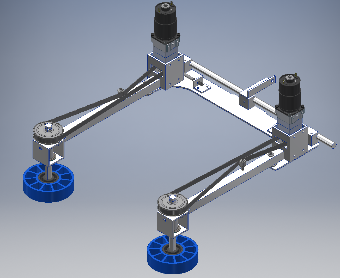
Current Intake
- Weight: 6.292 lb + fasteners
- 2 775pros geared with 5:1 and 3:1 for 15:1 reduction
- Things we need to document here:
- How is this held inside frame perimeter? With the 3/4" bore x4.0" stroke air cylinder extended, it puts pressure on a level that holds the assembly vertical or past vertical leaning into the robot.
- What kind of action or actuations make it "deploy" outward? When should this happen? Is it retractable after deployed? Retraction of the air cylinder will cause the intake subassembly to rotate CCW (facing the left side of the robot) 90 degrees to the fully deployed position. There is a hard stop. Actuaction should happen prior to intaking a cube. It is thought that the intake will remain retracted (for protection, until needed to intake a cube. Yes it is retractable after deployment..
- What is the intended operation of the 2 775's? Run always? Run until cube in place? Driver on/off manually? They run in opposite directions: Cube in, left motor runs CW, right one runs CCW. To expell a cube, left runs CCW, right runs CW. Driver should have control to start the intake. Cube in position at front frame rail or at arm roller pick up, the intake rollers should stop.
- Is there any articulation parallel to the ground? What controls that? It may be desirable to have the arms float, so that if hit from the front, the arms could move upward. At best the thought would be to remove air from the cylinder (both ports to vent). The intake rollers (4 in dia. wheels) will float on the hex drive shaft as well. One possible control option would be to give drivers a button the intakes while held down, and expells while another button is held down..
Current Cube Transport
- We have decided on an arm design.
- The plan is to be able to rotate 180+ degrees for easy Power Cube Zone to Exchange times.
- Things we need to document here:
- What actually moves on this thing? Only the pivot of the "shoulder" of the arm is obvious from the drawings. Rollers? Wheels? Top? Bottom? Both?
- What is the actual overall travel? (number of degrees total travel, from what angle with ground/frame to what angle?)
- What does the "U" on the end of the arm look like? Concept drawing? CAD? Anything?
- How does the hand-off from the intake to this work? (what angle to go to? what does intake need to do to be compatible with the hand off? what parts on this need to move in what way?)
- What is the intended operation to "score" on the switch? (what angle to go to? what needs to move?)
- What is the intended way to pass through to exchange? (what angle to go to? what needs to move?)
- How does the arm maintain a stable angular position? Will it backdrive?
- How does this thing know what it's angular position is? How can it be controlled?
- How does the cube-holding work? what keeps it in place?
- What is starting position?
- What is most stable position for high speed driving? Does this change with/without a cube?
Calculations have been done for the arm and the next task will be to figure out gearing and sprocket sizes to finalize the numbers.
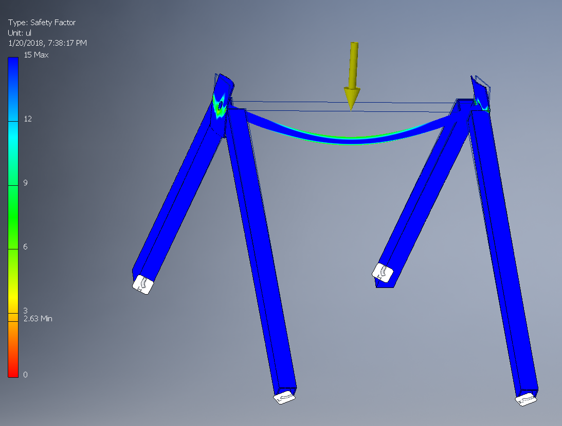
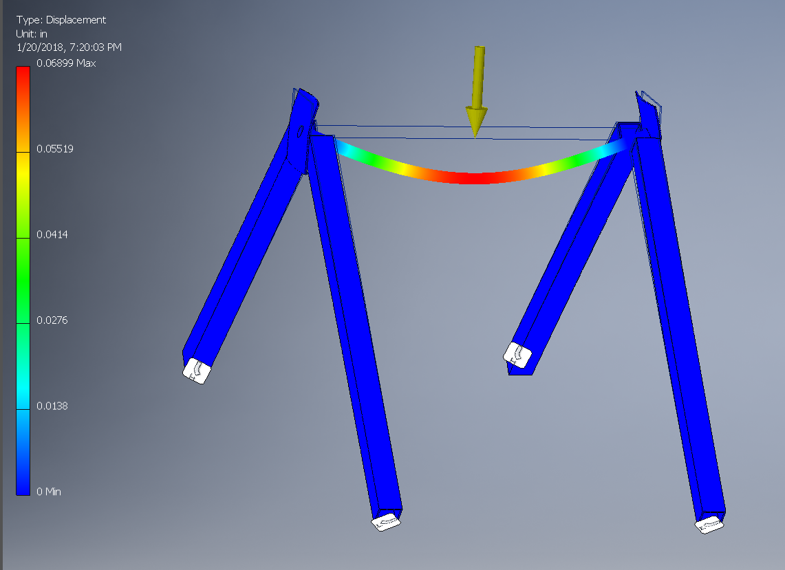
Stress Analysis
Meeting Notes
1/7 - Sunday:
- Intake:
- Started work on roller intake prototype
1/9 - Tuesday
- Intake:
- Put grooves in 4" compliance wheels to increase friction
- Arm tensioning moved to points on frame so they move independently
1/10 - Wednesday
- Intake:
- Belted motors to frame, now driving the rollers with drills will not affect the movement of arms
- Arm pivot point moved so they are 10.5" long, which makes sure we do not pick up multiple cubes at once.
1/11 - Thursday
- Intake
- 6 wheels on each roller. Now that wheels are contacting almost everywhere on the cube, the intake is more consistent and cube doesn't tilt as much on entry.
- Taped a lexan sheet to carpet to simulate something on the bottom of the intake. This alleviated some of the friction from the carpet once the cube entered the intake
- Almost finished mounting motors to arms so we don't have to drive it with drills.
- Arms are mounted to a C-channel on a hinge so we can start to look at what happens after intaking the cube (like lifting it up).
- Likely going to switch to 2" compliance wheels due to geometry inside the robot with the ramp.
1/13 - Saturday
- Intake:
- General robot design decision: intake will be separate from transport mechanism
- Motors mounted
- Added a roller to each arm that touches the ground instead of the wheel shaft.
- After playing with different amounts of wheels in different locations on the shaft, we determined that one wheel at the bottom is best because of how much lighter it is than having more wheels. This means it spins up quicker and also allows the arm to be more springy.
- We realized that lifting the cubes straight up while it touches the wheels is near impossible so that will need to be figured out.
- Could be as simple as actuating the arms outwards when we want to lift up the cube.
- We also began prototyping a roller, which consists of rubber stretched over a plastic tube. This is extremely light and it initially seems to have a ton more grip than any wheels.
- Matt D. is probably going to use these in a prototype of the arm/claw.
1/14 - Sunday
- Intake:
- Changed 775pros to MiniCIMs with 4:1 gearboxes for a total ratio of 8:1
- This worked much better than the 775pros.
- Calvin and Tom worked on 2D CAD sketches to show the geometry of the intake arms folding in and out.
1/16 - Tuesday
- Intake:
- Swapped pulleys on MiniCIMs for a total ratio of 2:1
- The wheels slipped a lot on the cube and this did not work as well as the 8:1 ratio.
1/20 - Saturday
- Intake
- Estimated weight: 6.292 lb (not including fasteners)
- Put parts on shopping list:
- Motors and gearboxes
- Bearings/Bushings
- Aluminum stock
Historical Design Documentation
Intake
Prototype Intake
- Side rollers with 1 blue compliance wheel on each side as close to the ground as possible.
- Rollers are on arms that can pivot outwards and are tensioned with surgical tubing attached to the frame.
- Rollers are belted to motors mounted on the arms.
- 2 775pros geared 30:1.
- Changed to MiniCIMs geared 8:1.
- 10.5" long arms.
- Intake must grab the cube in a way that when it flips over to the other side the cube is in the right position for the exchange.
- Capable of grabbing any cube it touches.
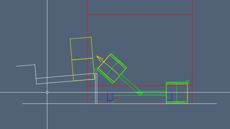
This drawing depicts how the intake would fold into the drive train.
- Note: this design is not being used, the intake now pivots up instead.
Transport
Time Trials
On 1/10/2018 time trials were conducted using past years' robots to determine how much driver control affected timings for picking up a CUBE and getting it to the EXCHANGE. Picking up, driving backwards and delivering the CUBE to the EXCHANGE was compared to picking up a CUBE, turning 180 degrees, abd delivering the CUBE to the EXCHANGE.
| 2016 | 2017 | AVERAGE | 16" FP Extensions | |
| 180 Degree Turn | 53 | 47 | 50 | 42 |
| Back & Forth | 35 | 33 | 34 | 27 |

