2014:Shooter Subteam: Difference between revisions
No edit summary |
Programming (talk | contribs) No edit summary |
||
| (23 intermediate revisions by 2 users not shown) | |||
| Line 19: | Line 19: | ||
=== Stress Analysis === | === Stress Analysis === | ||
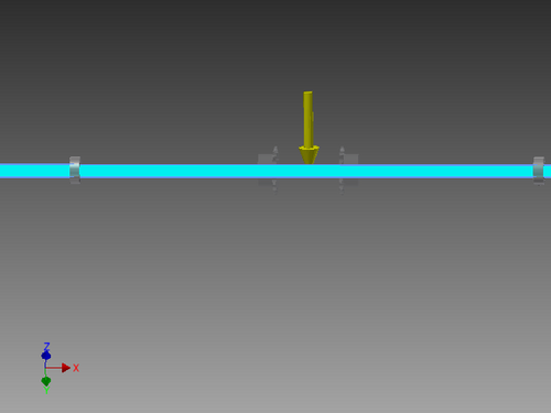
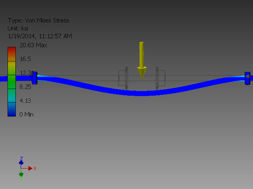
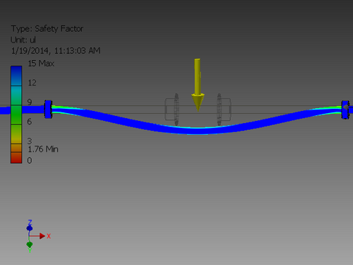
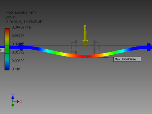
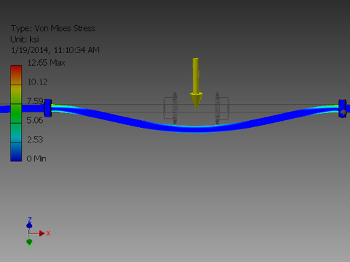
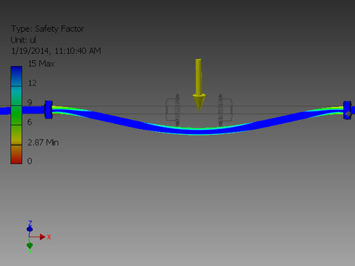
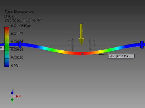
* | *An alumninum rod fixed where the bearings are | ||
[[File:Aluminumaxleconstraint.png|500px|Aluminumaxleconstraint.png]] | |||
---- | |||
[[File:Aluminumaxlestress.png|500px|Aluminumaxlestress.png]] | |||
---- | |||
[[File:Aluminumaxlesafetyfactor.png|500px|Aluminumaxlesafetyfactor.png]] | |||
---- | |||
[[File:Aluminumaxledisplacement.png|500px|Aluminumaxledisplacement.png]] | |||
---- | |||
*A steel rod fixed where the bearings are | |||
[[File:Steelaxlestress.png|500px|Steelaxlestress.png]] | |||
---- | |||
[[File:Steelsafetyfactor.png|500px|Steelsafetyfactor.png]] | |||
---- | |||
[[File:Steelaxledisplacement.png|500px|Steelaxledisplacement.png]] | |||
| <br/> | ||
| | ||
| Line 43: | Line 63: | ||
- Weight | - Weight | ||
*45 LBS | |||
- CIM motors | - CIM motors | ||
*4 mini CIM | |||
- | *2 regular CIM | ||
- Control | |||
*PWM or CAN, but PWM may be preferred as it may be faster | |||
*cRio CAN is derived from RS-232 with max data speed of 115,200 bps. | |||
= Thurs Jan 9 = | = Thurs Jan 9 = | ||
| Line 58: | Line 83: | ||
*Still working on Fundamentals for design | *Still working on Fundamentals for design | ||
*Calculating how far the kicker has to move | |||
* Calculating if motor driven is possible for Kicker | |||
*Calculating if motor driven is possible for Kicker | |||
*met with collection | *met with collection | ||
| Line 72: | Line 98: | ||
*How to stop kicker motion | *How to stop kicker motion | ||
*nylon strap | |||
* blocking plate | |||
*blocking plate | |||
== End of Day Design == | == End of Day Design == | ||
| Line 93: | Line 120: | ||
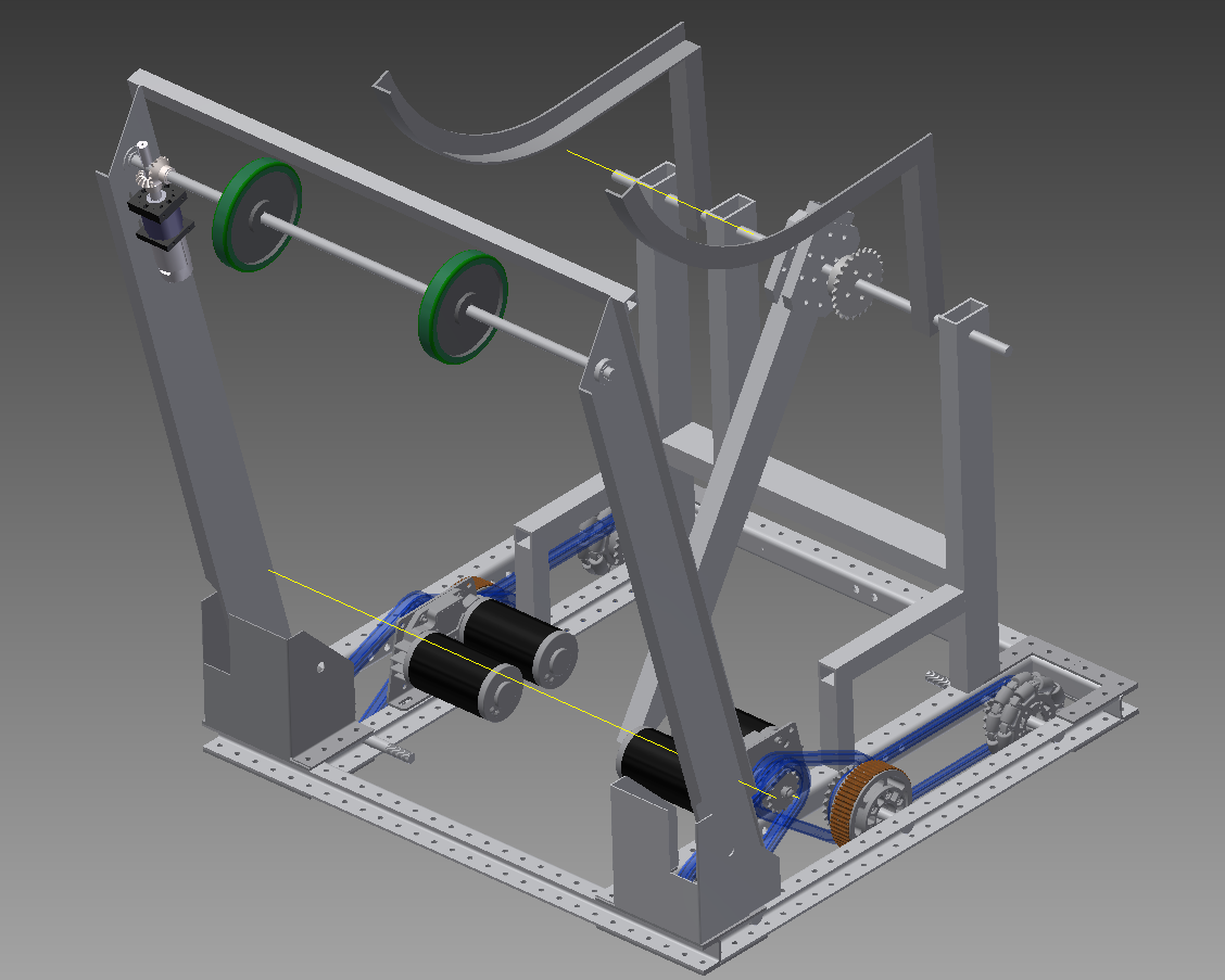
*Made a physical mock-up of the shooter | *Made a physical mock-up of the shooter | ||
-cradle | |||
*kicker | *kicker | ||
| Line 102: | Line 130: | ||
[[File:Shooterjan14.png]] | [[File:Shooterjan14.png]] | ||
= | = '''Sunday, January 26th''' = | ||
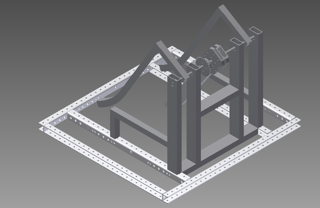
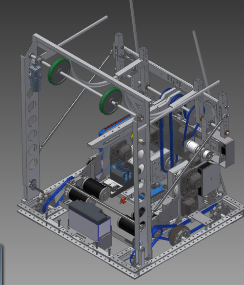
[[File:Robot 1-26-2014.PNG|500px|Robot_1-26-2014.PNG]] | |||
<br/>'''Overall Design:''' | |||
Electrical Components mostly placed. | |||
'''Kicker Restraint System:''' | |||
Uses a nylon strap (approx. 10,000lb tensile strength) to restrain the kicker. Springs mounted to drivetrain reduce the sudden stopping of the kicker by absorbing force from the strap. | |||
'''Spring Physics Calculations - ''' | |||
Desired Energy to achieve 10m/s Ball Velocity: 65 J (N/m) | |||
Note: Joules are the same as (Newtons * meters) | |||
Assumed Distance of Energy Transfer to Ball: 10 cm (0.1 m) | |||
KE = .5 * k * (d^2) : Derived From Hooke's Law using an Integral | |||
65 Nm / (.5 * (.1 m ^2) = k | |||
13000 N/m = k | |||
Conversions: | |||
Newtons = kg /9.8 m/sec^2 | |||
13000 N/m / 9.8 m/sec^2 = 1326 kg/m | |||
1 kg = 2.24 lb | |||
1326 kg/m * 2.24 (lb/kg) = 2971 lb/m | |||
39.37 in = 1 meter | |||
2971 lb/m / (39.37 in/meter) = '''75 lb /in = k''' | |||
'''Worst Case Scenario Shown - '''Motors will shut off before mechanical stop point, meaning energy transfer will not be as bad as shown. | |||
Springs Chosen - 4 Compression, 8.60 lb/in Rate, absorbed over 1.25" | |||
= | 8.60 lb/in * (1.25 in./ 1 in) * 4 springs = 43 lb/in overall | ||
Absorbs at least half of the force from the kicker. | |||
Latest revision as of 09:52, 26 January 2014
To do
To Be Done
- Finish design for Ball constraint in kicker
- Find where we need mechanical stops
- Raise battery
- Locate kicker stop
- Clearance for electrical
- Area (Bottom Pan for electrical between motors
- Side Restraints
Conflicts
- Kicker path and D.T. stabilizers
Design Analysis
Stress Analysis
- An alumninum rod fixed where the bearings are
- A steel rod fixed where the bearings are
Current Design
- shooting takes 1-2 seconds
- a kicker strikes the ball through 2 bars (cradle)
- Linked with intake with a motor in the cradle structure pulling and pushing intake
Equipment Requirements/Size
- Weight
- 45 LBS
- CIM motors
- 4 mini CIM
- 2 regular CIM
- Control
- PWM or CAN, but PWM may be preferred as it may be faster
- cRio CAN is derived from RS-232 with max data speed of 115,200 bps.
Thurs Jan 9
Sat Jan 11
- Still working on Fundamentals for design
- Calculating how far the kicker has to move
- Calculating if motor driven is possible for Kicker
- met with collection
- integrate our cradle with the collection
- What type of material should we use
- Better to have a longer kicker than a lighter one
Accomplishments/Results
- Kicker must move about 80 - 90 degrees
- If you go any less than that you need more motors
- How to stop kicker motion
- nylon strap
- blocking plate
End of Day Design
Sun Jan 12
- Continue work on 3D design in inventor
- Determine geometry of Our kicker to the ball and cradle
- Our kicker has to be curved at some point so that we get the max speed into the ball rather than rotation
- We Finished drive trains CAD
- Worked on CAD for shooter
Tues Jan 14
- worked more with intake to get a linkage working
- messed some more with the geometry of the shooter
- Made a physical mock-up of the shooter
-cradle
- kicker
- Worked more on the CAD mock-up
Current Design
Sunday, January 26th
Overall Design:
Electrical Components mostly placed.
Kicker Restraint System:
Uses a nylon strap (approx. 10,000lb tensile strength) to restrain the kicker. Springs mounted to drivetrain reduce the sudden stopping of the kicker by absorbing force from the strap.
Spring Physics Calculations -
Desired Energy to achieve 10m/s Ball Velocity: 65 J (N/m)
Note: Joules are the same as (Newtons * meters)
Assumed Distance of Energy Transfer to Ball: 10 cm (0.1 m)
KE = .5 * k * (d^2) : Derived From Hooke's Law using an Integral
65 Nm / (.5 * (.1 m ^2) = k
13000 N/m = k
Conversions:
Newtons = kg /9.8 m/sec^2
13000 N/m / 9.8 m/sec^2 = 1326 kg/m
1 kg = 2.24 lb
1326 kg/m * 2.24 (lb/kg) = 2971 lb/m
39.37 in = 1 meter
2971 lb/m / (39.37 in/meter) = 75 lb /in = k
Worst Case Scenario Shown - Motors will shut off before mechanical stop point, meaning energy transfer will not be as bad as shown.
Springs Chosen - 4 Compression, 8.60 lb/in Rate, absorbed over 1.25"
8.60 lb/in * (1.25 in./ 1 in) * 4 springs = 43 lb/in overall
Absorbs at least half of the force from the kicker.
