2014:Electrical Controls Subteam: Difference between revisions
Programming (talk | contribs) No edit summary |
No edit summary |
||
| (8 intermediate revisions by 2 users not shown) | |||
| Line 6: | Line 6: | ||
*use actual items from each of the previous year's controls (see 1/12/14 notes) | *use actual items from each of the previous year's controls (see 1/12/14 notes) | ||
* | *Base is red, like the robot's chassis. Lids are black, like the robots moving parts. | ||
*no lights for the broken switches (not many switches will be used and they have an on/off tag built into them) | *no lights for the broken switches (not many switches will be used and they have an on/off tag built into them) | ||
*'underglow': will come out the letter cutouts | *'underglow': will come out the letter cutouts | ||
| Line 16: | Line 16: | ||
== Current Design State == | == Current Design State == | ||
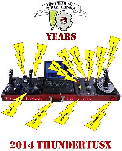
[[File: | [[File:ControlsFlyer2014.jpg|400px|ControlsFlyer2014.jpg]]<br/>NOTE: click to view larger image | ||
== Todo == | == Todo == | ||
| Line 31: | Line 31: | ||
| need to get the info documented on the wiki | | need to get the info documented on the wiki | ||
|- | |- | ||
| | | started 1/21 | ||
| how will underglow be controlled | | how will underglow be controlled | ||
| | | will use PWM on Teensy. possibly make use of extra pot, hip check and/or missile switch | ||
|- | |- | ||
| | | started 2/1 | ||
| wire controls | | wire controls | ||
| | | | ||
|- | |- | ||
| | | started 1/28 | ||
| get camera library for SmartDashboard | | get camera library for SmartDashboard | ||
| | | | ||
|- | |- | ||
| | | started 1/30 | ||
| design SmartDashboard layout | | design SmartDashboard layout | ||
| | | | ||
|- | |- | ||
| | | started 1/18 | ||
| code SmartDashboard | | code SmartDashboard | ||
| | | | ||
|- | |- | ||
| | | started 2/25 | ||
| code SmartDashboard hot goal detection | | code SmartDashboard hot goal detection | ||
| | | | ||
| Line 98: | Line 90: | ||
| complete the parts list | | complete the parts list | ||
| | | | ||
|- completed 2/1 | |||
| not started | |||
| paint controls | |||
| | |||
|- | |||
| completed 2/4 | |||
| talk about color scheme | |||
| Base is red, like the robot's chassis. Lids are black, like the robots moving parts.<br\>Will not do each year's color scheme; will detract from the simple read & black. | |||
|} | |} | ||
== Teensy Links == | == Teensy Info == | ||
===Teensy Links=== | |||
[http://hamaluik.com/posts/making-a-custom-teensy3-hid-joystick/ Making A Custom Teensy3 HID Joystick]<br/> | [http://hamaluik.com/posts/making-a-custom-teensy3-hid-joystick/ Making A Custom Teensy3 HID Joystick]<br/> | ||
[http://www.pjrc.com/teensy/td_joystick.html Teensy Joystick examples]<br/> | [http://www.pjrc.com/teensy/td_joystick.html Teensy Joystick examples]<br/> | ||
[http://www.pjrc.com/teensy/td_digital.html Digital IO examples] NOTE: Teensy has built-in pull-up resistors<br/> | [http://www.pjrc.com/teensy/td_digital.html Digital IO examples] NOTE: Teensy has built-in pull-up resistors<br/> | ||
=== Running Teensy3.1 === | |||
*Step 1-have arduino | |||
*Step 2-Go to https://www.pjrc.com/teen/loader.html and download Teensy.exe | |||
*Step 3-Download Teensyduino Here-https://www.pjrc.com/teensy/td_download.html | |||
*Step 4 Run Teensyduino | |||
*Step 5 open arduino and go to tools and change the board to teensy3.1 | |||
*Step 6-Change Usb type in tools to Joystick | |||
*Step 7-Open a teensy example and begin | |||
*Step 8-Run Teensy.exe to upload | |||
= Engineering Notebook = | = Engineering Notebook = | ||
| Line 136: | Line 145: | ||
|- | |- | ||
| rowspan="2" | '06 Roflbot | | rowspan="2" | '06 Roflbot | ||
| | | lexan from controls | ||
| behind cut out letters and shine underglow throw it | | behind cut out letters and shine underglow throw it | ||
|- | |- | ||
| Line 260: | Line 269: | ||
== 1/18/14 == | == 1/18/14 == | ||
Attendance: Chris, Gunnar, Mr. Byers, Eric | |||
We finished the CAD work and stared to create the sketches to send to Harris. We also worked on the shopping list and decided that we are going to use Teensy 3.1 board to make it so the computer sees the aux buttons as a joystick. | We finished the CAD work and stared to create the sketches to send to Harris. We also worked on the shopping list and decided that we are going to use Teensy 3.1 board to make it so the computer sees the aux buttons as a joystick. | ||
| Line 277: | Line 286: | ||
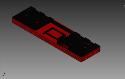
[[File:ControlsAssembly2014.PNG|400px|ControlsAssembly2014.PNG]]<br/>NOTE: click to view larger image | [[File:ControlsAssembly2014.PNG|400px|ControlsAssembly2014.PNG]]<br/>NOTE: click to view larger image | ||
| Line 319: | Line 329: | ||
We finished mapping out the buttons and switches to the teensy and then put it into an excel document. Then we created the schematic in multisim, which is located in the electrical controls folder. Finished CADing the 3D print buttons and sent the files out. | We finished mapping out the buttons and switches to the teensy and then put it into an excel document. Then we created the schematic in multisim, which is located in the electrical controls folder. Finished CADing the 3D print buttons and sent the files out. | ||
| |||
== 2/1/14 == | |||
Attendance: Gunnar, Chris, Mr. Byers, Eric | |||
*Received metal parts from Harris and verified fit of controls. | |||
*Determined hinge mounting. | |||
*Made corner brackets and pre-drilled rivet holes. | |||
*Painted all parts, including rivets and numbers along back. | |||
*Attached corner brackets. | |||
*Attached lexan behind letters. | |||
*Circuit board cut to size, location picked, and connectors mounted and labeled. | |||
== 2/2/14 == | |||
Attendance: Chris, Mr. Byers, Jeff B. | |||
*Mounted: hinges, latches, circuit board stand-offs, laptop bracket, joysticks | |||
*Threaded set screw into turret knob. | |||
*Determined location for light strip. | |||
*Download software for Teensy board and was able to get the sample programmed into it. | |||
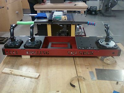
[[File:ControlsPart12014.jpg|400px|ControlsPart12014.jpg]]<br/>NOTE: click to view larger image | |||
== 2/4/14 == | |||
Attendance: Chris, Mr. Byers, Eric, Jeff B. | |||
*Received 3D printed knobs from Harris. | |||
*Mounted: handle, usb hub | |||
*Download software for Teensy board onto another laptop. Confirmed PC saw Teensy as a joystick. | |||
* ??? | |||
== 2/5/14 == | |||
No meeting. After school activies canceled. | |||
== 2/6/14 == | |||
Attendance: Chris, Gunnar, Jeff B., Mr. Byers | |||
We painted the 3D pinted buttons. The lightning bolt bright yellow and the gear grey. Gunnar began woking on wiring the teensy. All of the buttons were put in place. We decided the length of light string we need. We will need about 8 ft. We also talked with the programers about how we can change the light patterns, and what each light pattern will be. | |||
== 2/7/14 == | |||
Attendance: Gunnar, Chris, Austin | |||
*Continued to wire the Teensy. | |||
*Wired the broken switches and 3D print buttons. | |||
*Made the connector for minibot battery to LED connector. | |||
*Began testing LED time for the battery. | |||
Latest revision as of 17:52, 18 January 2015
Electrical Controls Design
Overview
- use actual items from each of the previous year's controls (see 1/12/14 notes)
- Base is red, like the robot's chassis. Lids are black, like the robots moving parts.
- no lights for the broken switches (not many switches will be used and they have an on/off tag built into them)
- 'underglow': will come out the letter cutouts
- speakers (TBD)
- Click here for joystick and SmartDashboard mapping tables
Current Design State

NOTE: click to view larger image
Todo
| Status | Item | Details |
| started 1/9 | get updated network tables for SmartDashboard | need to get the info documented on the wiki |
| started 1/21 | how will underglow be controlled | will use PWM on Teensy. possibly make use of extra pot, hip check and/or missile switch |
| started 2/1 | wire controls | |
| started 1/28 | get camera library for SmartDashboard | |
| started 1/30 | design SmartDashboard layout | |
| started 1/18 | code SmartDashboard | |
| started 2/25 | code SmartDashboard hot goal detection | |
| completed 1/14 | decide if gear button is a 'normal' one or a push-pot | 'normal' |
| completed 1/14 | decide if backpack straps are needed | will not add them |
| completed 1/18 | get paper sketch into inventor | |
| completed 1/18 | determine what will be used to map the buttons to a joystick | Tweensy 3.1 (arduino) |
| completed 1/18 | number of broken switches (with hip check can only have 5; but if hip check is handled within controls, we can have a 6th broken switch) | make holes for 6, worry about wiring later |
| completed 1/18 | how to attach hinges (need to stay within 14" depth) | panels will have notches for rounded part of hinge, and then 1/8" rivets |
| completed 1/19 | do we use audio add-on board or PC to generate sound | FRC dashboard can only handle 12 buttons, but it does 6 axis. so we would convert hip check button into an axis. This will get all the info to the robot and then it can send it to the SmartDashboard, then the SmartDashboard can play the sounds. |
| completed 1/21 | send drawings to Harris | |
| completed 1/21 | complete the parts list | |
| not started | paint controls | |
| completed 2/4 | talk about color scheme | Base is red, like the robot's chassis. Lids are black, like the robots moving parts.<br\>Will not do each year's color scheme; will detract from the simple read & black. |
Teensy Info
Teensy Links
Making A Custom Teensy3 HID Joystick
Teensy Joystick examples
Digital IO examples NOTE: Teensy has built-in pull-up resistors
Running Teensy3.1
- Step 1-have arduino
- Step 2-Go to https://www.pjrc.com/teen/loader.html and download Teensy.exe
- Step 3-Download Teensyduino Here-https://www.pjrc.com/teensy/td_download.html
- Step 4 Run Teensyduino
- Step 5 open arduino and go to tools and change the board to teensy3.1
- Step 6-Change Usb type in tools to Joystick
- Step 7-Open a teensy example and begin
- Step 8-Run Teensy.exe to upload
Engineering Notebook
1/9/14
Looked at prior year controls.
Talked in general about what the sub-team will need to do.
1/12/14
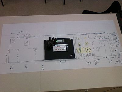
Prototype

NOTE: click to view larger image
Design Ideas
To celebrate 10th year, we will use physical parts for each of the prior year robots.
| Year | Potential Item | Where It Will Be Used |
| '05 Rinobot | operator interface | |
| hinges from controls | hinges for the lids | |
| '06 Roflbot | lexan from controls | behind cut out letters and shine underglow throw it |
| silver knob from controls | knob for extra pot | |
| '07 Aracnaphobia | broken switches | |
| missile switch | ||
| joystick | aux driver joystick | |
| '08 Mach 1511 | missile swtich | |
| broken switches | broken switches | |
| '09 ThunderPlucker | handle | |
| Ethernet port | ||
| dull 3-way switch | autonomous selection | |
| coin button | hip check button | |
| '10 ThunderFoot | handle | handle |
| '11 ThunderusPrime | hand painted tanks | TBD |
| robot USB hub | usb hub | |
| 3 position switch | ||
| keypad | ||
| handles | ||
| '12 ThunderStorm | 7 seg display | |
| cube | ||
| turret knob | manual shooter strength knob | |
| usb hub | ||
| ethernet port | ||
| '13 ThunderPrise | latches | |
| 4th joystick circuit board | ||
| driver joysticks | driver joysticks |
Mtg Minutes (with Strategy)
- aux joystick:
- Y axis for intake
- trigger roller in
- 'thumb' button roller out
- 'top' button for fast roller out
- big button for high goal kick (gear)
- button for truss kick (lightning bolt)
- manual shoot power (pick one of the following:
- launch button [auto vs man kick]
- slider w/button for manual kick power
- a pot with gear for the knob
- 3 position switch for autonomous selection (none, 1 ball, 2 ball)
- light on intake side & smartdashboard when intake is fully up
- light on intake side, shooting side & smartdashboard when ball is acquired (not on ground)
1/14/14
Attendace: Gunnar, Chris, Mr. Byers, Eric, Gordan
We worked on CAD and deciding how we wanted to approach making the lightning bolt and gear buttons.
1/15/14
Attendance: Chris, Mr. Byers, Gordan
The CAD model was worked on.
1/16/14
Attendance: Chris, Gunnar, Mr. Byers
Data sheets for some of the switches were found and the CAD model is close to completion.
1/18/14
Attendance: Chris, Gunnar, Mr. Byers, Eric
We finished the CAD work and stared to create the sketches to send to Harris. We also worked on the shopping list and decided that we are going to use Teensy 3.1 board to make it so the computer sees the aux buttons as a joystick.
1/19/14
Attendane: Chris, Mr. Byers (at home)
Finished looking at the audio add-on board for the Teensy 3.1. The FRC dashboard can only handle 12 buttons, but 6 axis. So we will use the Teensy to convert the hip check button into one of the axis. The SmartDashboard will play the sound via the PC (robot will need to send button presses to SmartDashboard). This will also free up the Teensy pins that were needed for the audio add-on, thus making the Tweesy wiring easier to deal with. Plus it separates the 'risk' with the audio from the required button functionality.
1/21/14
Attendance: Chris, Gunnar, Eric
Amy came in and tought us how to do drawings correctly in inventor. We also finised the parts list and took the hinges off of 2005.
NOTE: click to view larger image
1/22/14
Attendance: Chris
Updated the operator control tables.
1/23/14
Attendance: Gunnar, Chris, Eric, Gordan, Jeff B
Collected some parts we needed from past robots.
1/25/14
Attendance: Chris, Gunnar, Mr. Byers, Eric
We finished gathering parts from old controls and marked down what we need to replace. Need to request epoxy to fill knob and make it the proper size. Created and tested the ethernet adapter. Sorted through the RBG strips and claimed the multi-colored strips. The 3d printed buttons were worked on in inventor.
1/26/14
We did not do much for controls. Chris worked in the machine shop for most of the day.
1/28/14
Attendance: Chris, Jeff B., Mr. Byers, Eric.
We eppoxied the hole in the 3D printed dial from 2012 controls so we could drill a smaler hole. The smaler hole is to accomidate for the new push potentiometer (which is very small). After making a mess with the epoxy, we filled and sanded off the excess.
1/29/14
Attendance: Chris, Gunnar, Mr. Byers
We worked on mapping the buttons to the teensy. We also worked on making 1:1 stencil numbers for the back of the controls. The stencils we printed out the 1:1 image from inventor and cut the numebrs out with exacto knoves. The numbers will either be spray painted, or sponged on to the back face if the base of the controls. There is a number for each year the team has been in first for out 10th year aniversery. We also finished up the cad for the 3D printed buttons (the lightning bolt and gear).
1/30/14
Attendance: Gunnar, Chris, Mr. Byers, Eric
We finished mapping out the buttons and switches to the teensy and then put it into an excel document. Then we created the schematic in multisim, which is located in the electrical controls folder. Finished CADing the 3D print buttons and sent the files out.
2/1/14
Attendance: Gunnar, Chris, Mr. Byers, Eric
- Received metal parts from Harris and verified fit of controls.
- Determined hinge mounting.
- Made corner brackets and pre-drilled rivet holes.
- Painted all parts, including rivets and numbers along back.
- Attached corner brackets.
- Attached lexan behind letters.
- Circuit board cut to size, location picked, and connectors mounted and labeled.
2/2/14
Attendance: Chris, Mr. Byers, Jeff B.
- Mounted: hinges, latches, circuit board stand-offs, laptop bracket, joysticks
- Threaded set screw into turret knob.
- Determined location for light strip.
- Download software for Teensy board and was able to get the sample programmed into it.

NOTE: click to view larger image
2/4/14
Attendance: Chris, Mr. Byers, Eric, Jeff B.
- Received 3D printed knobs from Harris.
- Mounted: handle, usb hub
- Download software for Teensy board onto another laptop. Confirmed PC saw Teensy as a joystick.
- ???
2/5/14
No meeting. After school activies canceled.
2/6/14
Attendance: Chris, Gunnar, Jeff B., Mr. Byers
We painted the 3D pinted buttons. The lightning bolt bright yellow and the gear grey. Gunnar began woking on wiring the teensy. All of the buttons were put in place. We decided the length of light string we need. We will need about 8 ft. We also talked with the programers about how we can change the light patterns, and what each light pattern will be.
2/7/14
Attendance: Gunnar, Chris, Austin
- Continued to wire the Teensy.
- Wired the broken switches and 3D print buttons.
- Made the connector for minibot battery to LED connector.
- Began testing LED time for the battery.
