2009:Robot Design Details: Difference between revisions
From 1511Wookiee
Jump to navigationJump to search
Programming (talk | contribs) No edit summary |
m (Robot Design Details moved to 2009:Robot Design Details) |
||
| (6 intermediate revisions by 3 users not shown) | |||
| Line 5: | Line 5: | ||
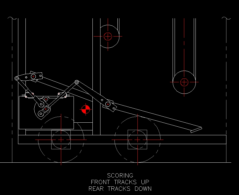
[[Image:Scoring 1.jpg|424x300px]] [[Image:Empty Cell 1.jpg|247x225px]] [[Image:Collecting 1.jpg|236x225px]]<br> | [[Image:Scoring 1.jpg|424x300px]] [[Image:Empty Cell 1.jpg|247x225px]] [[Image:Collecting 1.jpg|236x225px]]<br> | ||
[[Image:Dimensions 1-19-09.jpg|400x400px]] | [[Image:Dimensions 1-19-09.jpg|400x400px]][[Image:Robot_2_1-25-2009.jpg|400x300px]] | ||
== Drivetrain<br> == | == Drivetrain<br> == | ||
| Line 42: | Line 42: | ||
*Two [http://sccatalog.honeywell.com/pdbdownload/images/v7-2b17d8-048.pdf Limit Switches] to tell when door is in open/closed position | *Two [http://sccatalog.honeywell.com/pdbdownload/images/v7-2b17d8-048.pdf Limit Switches] to tell when door is in open/closed position | ||
<br> <br> <br> | [[Image:Limit Switches Collecting.jpg]] | ||
[[Image:Limit_Switches_Scoring.jpg]]<br> <br> <br> | |||
== Ball Hopper == | == Ball Hopper == | ||
| Line 49: | Line 55: | ||
*Entry from conveyor at top of robot; entry controlled by upper ejector | *Entry from conveyor at top of robot; entry controlled by upper ejector | ||
*Exit is a "trap door" at the bottom of the hopper down to the area behind the lower ball collector and at the base of the conveyor system. | *Exit is a "trap door" at the bottom of the hopper down to the area behind the lower ball collector and at the base of the conveyor system. | ||
*Trap door powered by Nippon Denso Window motor (along with lower collection blocker | *Trap door powered by Nippon Denso Window motor (along with lower collection blocker) | ||
*Two [http://sccatalog.honeywell.com/pdbdownload/images/v7-2b17d8-048.pdf Limit Switches] to tell when door is in open/closed position | *Two [http://sccatalog.honeywell.com/pdbdownload/images/v7-2b17d8-048.pdf Limit Switches] to tell when door is in open/closed position | ||
*Jaguar speed controller | *Jaguar speed controller | ||
| Line 57: | Line 63: | ||
*Two conveyors opposite each other, working together to move balls from ball intake and/or below the ball hopper up to the upper ball ejector/hopper entry point. | *Two conveyors opposite each other, working together to move balls from ball intake and/or below the ball hopper up to the upper ball ejector/hopper entry point. | ||
*Front conveyor also acts as collector to bring outside balls in via "chicken pluckers" on lower roller of conveyor | *Front conveyor also acts as collector to bring outside balls in via "chicken pluckers" on lower roller of conveyor | ||
*Powered by two independent motors ( | *Powered by two independent motors (Fischer Price** motors with [http://banebots.com/pc/MP-36XXX-545/MP-36025-545 25:1 reduction gearboxes]) **Changed from RS-545 | ||
*Likely NOT direct drive, will likey be chain/sprocket to save space and move weight back on robot | *Likely NOT direct drive, will likey be chain/sprocket to save space and move weight back on robot | ||
*Banner Sensors (photoelectric): [http://www.bannerengineering-online.com/pdf/Banner%20Q10.pdf Q10RP6R] Reciever and [http://www.bannerengineering-online.com/pdf/Banner%20Q10.pdf Q106E] Source Mounted at the top of conveyor to detect ball "ready to fire" | *Banner Sensors (photoelectric): [http://www.bannerengineering-online.com/pdf/Banner%20Q10.pdf Q10RP6R] Reciever and [http://www.bannerengineering-online.com/pdf/Banner%20Q10.pdf Q106E] Source Mounted at the top of conveyor to detect ball "ready to fire" | ||
| Line 63: | Line 69: | ||
*Jaguar speed controller | *Jaguar speed controller | ||
<br><br> | <br><br> | ||
== Upper Ball Ejector == | == Upper Ball Ejector == | ||
*Spinning ejector directs, based on direction, balls out of robot or in to hopper entry point. | *Spinning ejector directs, based on direction, balls out of robot or in to hopper entry point. | ||
*Powered by | *Powered by RS-545 Banebots** motor with plastic gearbox removed and 25:1 reduction gearbox added (same Banebots units as on conveyor drives) ** changed from Fischer Price | ||
*Will be chain/sprocket to save space and move weight back on robot, and to allow optimization of ejector speed without loss of motor power | *Will be chain/sprocket to save space and move weight back on robot, and to allow optimization of ejector speed without loss of motor power | ||
*Shaft encoder sensor ([http://usdigital.com/assets/general/91_e7p_datasheet_1.pdf E7P-180-375-S-H-G-3]) to monitor rotational speed (180 CPR). Requires 3/8" shaft. If we can't get [http://usdigital.com/assets/general/91_e7p_datasheet_1.pdf E7P] in time, we may have to use E4P model which requires 1/4" shaft | *Shaft encoder sensor ([http://usdigital.com/assets/general/91_e7p_datasheet_1.pdf E7P-180-375-S-H-G-3]) to monitor rotational speed (180 CPR). Requires 3/8" shaft. If we can't get [http://usdigital.com/assets/general/91_e7p_datasheet_1.pdf E7P] in time, we may have to use E4P model which requires 1/4" shaft | ||
*Jaguar speed controller | *Jaguar speed controller | ||
Latest revision as of 11:50, 4 January 2010
Main Robot Design
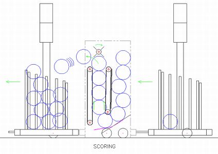
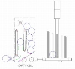
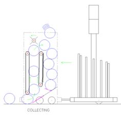
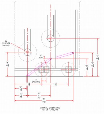
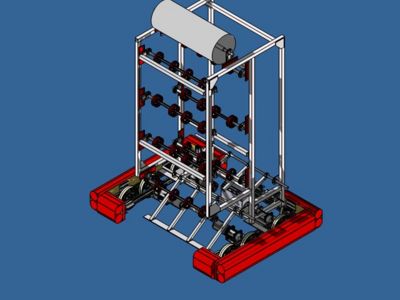
General layout design of the robot, Dimensions ARE NOT exact.
Drivetrain
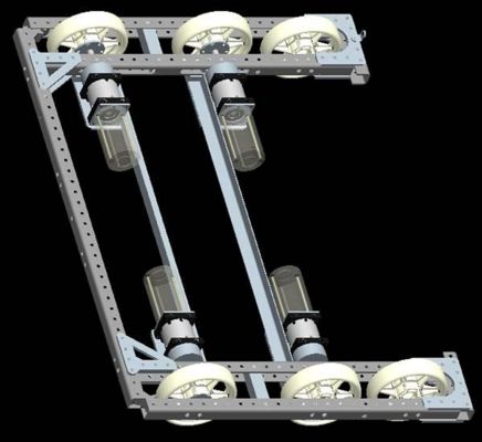
- 4-wheel drive(6 if needed)
- Four Banebots 12:1 Transmissions
- Four 2.5" CIM motors
- Victor 884 [Drive] Speed Controllers
- Fixed wheels (slip-style steering)
- Banebots encoders on each wheel (http://banebots.com/pc/ELECTRONICS/EN-G0561-KT) -- mounted at transmission outputs.
- 27.25” LONG x 37.25” WIDE
- Rear wheel axis at 5.625 from most rear surfaces (adjustable down to 4.625 corner brace regime permitting)
- Front wheel axis at 11.625 from front most surfaces (adjustable ± 2.00”)
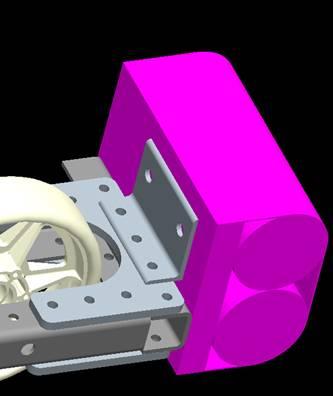
- Using 3/8" bolts to mount bumpers to the frame. See drawing below for bumper mount details.
- Spacers used will be copper pipe cut to the correct length to space wheels on the axel.
- 6 hole patterns in the wheels need to be tapped for 10-32 screws 3/4" deep
- No stiffener element between the wheels seems to be needed.
- Trailer hitch is assembled from KOP items.
- Determination of need to mount dummy wheels will occur once the top portion of the robot is assembled.
- Dummy wheels will be supported using 3/8" bolt, length TBD.
- Bearings will be inserted in the dummy wheels from the kit of parts.
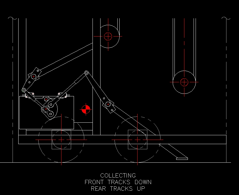
Front Ball Entry/Exit
- Ball intake/expulsion power provided by "chicken pluckers" on front conveyor - see conveyor.
- Passage controlled by "door" (TBD - need details)
- Front opening dimensions (TBD)
- Powered by same motor, speed controller as ball hopper trap door (see below).
- Two Limit Switches to tell when door is in open/closed position
Ball Hopper
- Open top entry for human player introduction
- Entry from conveyor at top of robot; entry controlled by upper ejector
- Exit is a "trap door" at the bottom of the hopper down to the area behind the lower ball collector and at the base of the conveyor system.
- Trap door powered by Nippon Denso Window motor (along with lower collection blocker)
- Two Limit Switches to tell when door is in open/closed position
- Jaguar speed controller
Ball Conveyor
- Two conveyors opposite each other, working together to move balls from ball intake and/or below the ball hopper up to the upper ball ejector/hopper entry point.
- Front conveyor also acts as collector to bring outside balls in via "chicken pluckers" on lower roller of conveyor
- Powered by two independent motors (Fischer Price** motors with 25:1 reduction gearboxes) **Changed from RS-545
- Likely NOT direct drive, will likey be chain/sprocket to save space and move weight back on robot
- Banner Sensors (photoelectric): Q10RP6R Reciever and Q106E Source Mounted at the top of conveyor to detect ball "ready to fire"
- 2 Omron photoelectric sensors arranged with a small wheel used to determine conveyor speed. One disk/sensor per conveyor.
- Jaguar speed controller
Upper Ball Ejector
- Spinning ejector directs, based on direction, balls out of robot or in to hopper entry point.
- Powered by RS-545 Banebots** motor with plastic gearbox removed and 25:1 reduction gearbox added (same Banebots units as on conveyor drives) ** changed from Fischer Price
- Will be chain/sprocket to save space and move weight back on robot, and to allow optimization of ejector speed without loss of motor power
- Shaft encoder sensor (E7P-180-375-S-H-G-3) to monitor rotational speed (180 CPR). Requires 3/8" shaft. If we can't get E7P in time, we may have to use E4P model which requires 1/4" shaft
- Jaguar speed controller
