2018:Drivetrain: Difference between revisions
Drivetrain (talk | contribs) No edit summary |
Drivetrain (talk | contribs) No edit summary |
||
| (43 intermediate revisions by 4 users not shown) | |||
| Line 1: | Line 1: | ||
< | <div class="mw-parser-output"><div class="mw-parser-output"><div class="mw-parser-output"><div class="mw-parser-output"> | ||
== Drive Base Subteam == | |||
<div class="mw-parser-output"><div class="mw-parser-output"> | |||
==== Leads: Ben S, Jordan S, Julia P ==== | |||
'''Sensors''' | |||
*Grayhill Inc. 63R256 Optical Encoders | |||
*Mounted on the center drive wheel shaft(colson wheel) on either side of the drivebase | |||
===== '''<span style="font-size:larger;">Drive base size</span>''' ===== | |||
*27 3/4" x 32 3/4" | |||
**34 3/4" x 39 3/4" (with bumpers) | |||
**ground clearance is 1.25 inches | |||
**Top of Drive Base is currently at 4.25 inches with total gear clearance at 4.83 inches. '''This is correcting the note that said the top was at 4.5 inches!''' | |||
**front rail at 4.5 inches from the front of the frame for cube collector mechansim. | |||
**1/16 - arm is connecting to rail across the front, cube intake is intending to attach in front of the arm connection, on the diagonal frame supports. (from integration 1/16) | |||
**6 cims on 40 amp Breakers | |||
**Bumpers will be 2" off the ground and overall 7" up | |||
===== <span style="font-size:larger;">'''6 wheels'''</span> ===== | |||
*4 omni wheels with 2 colsen center wheels | |||
**<s>6 Colson wheels will be tested</s> | |||
'''gear actuated''' | |||
*gear ratio: 14-64 | |||
'''frame''' | |||
*TBD: See discussion above on robot constraints. Connection needs and support needs of other mechanisms. Top priorities from integration is to locate the battery. Will need to know the location of the cube manupulator pivot point. | |||
Current | |||
1/23/2018 | |||
Today the drive train sub team is working on fabrication of parts and working more on detailing our parts, members of the team assembled parts for further fabrication and packaged parts to be put on the drive train shelving unit. Other members of our team are working on further detailing and precision on the CAD drive train drawing. | |||
| |||
Working on developing cross supports. Discussion with cube intake group occurred today. Priority will be on starting the 3-d printing of the spacers. (completed 1/16) This is how our CAD assembly looks currently. Not all the way done; but it is almost there! Encoder selection completed on 1/16 | |||
[[File:2018 Final Robot Assembly - Drive Train (1-23-18).png|RTENOTITLE]]</div> </div> </div> | |||
== Daily Journal Follows: == | |||
<u>1/20/2018</u> | |||
<u>[[File:Saftey factor bumper.PNG|RTENOTITLE]]</u> | |||
<u>w</u>e can use one churro tube saving .125 pounds per side and still have a safty factor up to 1500lbs. | |||
<u>[[File:Disnplacement 500 lbs bumper.PNG|RTENOTITLE]]</u> | |||
<u>1/16/2018</u> | |||
Right now we are busy at work with finishing designs and drawings in CAD, Julia and Jordan are working on printing parts with the printer, and we added a few more items to the shopping list. | |||
<u>1/14/2018</u> | |||
Significant progress on frame. Front and back supports were designed. Discussion on placement of cube intake puts the inside of the'''front rail at 4.5 inches from the front of the frame'''. Corner support brackets as well as the floor pan for supporting the batteries were put into CAD. Encoder Mount was designed. First parts were converted to part drawings. Roseanne had requested parts to go to Harris to see what level of support they could give. More stuff added to the shopping list. | |||
CAD is almost done and drawings have been started. Below is a picture of the cutout for the back brace of the robot with 2000 psi. | |||
[[File:Front cut out.PNG|RTENOTITLE]] | |||
<u>1/13/2018</u> | |||
CAD model of the gear and wheel assemblies are close to being completed and the development of the cross members has started. Waiting for first integration meeting to see what connection points will be requested by the cube management and robot lifting ramps will be needed. | |||
Weights researched on 1/11/18 were used to update the CAD model to verify the weights developed in the CAD Model. 8 pm estimated weight is just under 34 lbs with cross connections still needed. | |||
New sketch for key dimensions: | |||
[[File:Drivebase Dimensions.PNG|RTENOTITLE]] | |||
| |||
Mr Stoeckl did a finite element analysis (FEA) of the frame talking 1000 pound force from a bump and/or from a hit. This is the displacement: | |||
[[File:Frame Displacement Analysis.png|RTENOTITLE]] | |||
And here is the image showing the safety factor: | |||
[[File:Frame Safety Factor.png|RTENOTITLE]] | |||
| |||
<u>1/11/2018</u> | |||
We determined the U-shaped rails, and ordered the material needed for it. Mentors had a late night discussion last night about the gears on the drive train, specificlly the idler gears and changing them from the 64 tooth to another size, as of now, a 72 tooth is in consideration. Plans for tonight are to work with CADing the drive base, as well as finalizing part orders. Our seconday goal is to get to work on a weight table. Below is all the dimensions you could possibly want and more for our drivetrain cad. | |||
[[File:Dimensions 1-11-18.PNG|RTENOTITLE]] | |||
Weight Table created and added columns with information that will be handy when constructing the CAW (Cost Assessment Worksheet / a.k.a. BOM). Weight of gear and wheel assemblies is approx 33 lbs. This does not include cross braces and the plate planned for motor support. | |||
| |||
<u>1/10/2018</u> | |||
Design descisions: U shaped rails to support wheels, 4 omni and 2 colson, and a 14:64 gear ratio. Goal for tonight is to get a great start on the CAD model and identify things to go on the shopping list. | Design descisions: U shaped rails to support wheels, 4 omni and 2 colson, and a 14:64 gear ratio. Goal for tonight is to get a great start on the CAD model and identify things to go on the shopping list. | ||
| Line 17: | Line 115: | ||
Shopping to check aluminum gear proces for Pocketed vs non-pocketed: West Coast Products offered a pocketed VexPro Gear. 64 tooth gear cost +$4 when pocketed by WCP. 0.183 lbs per gear reduction, all 18 gears would be 3.3 lb reduction and cost $72. Just doing the 6 gears with load will save 1.1 lbs and cost $24. We could put holes through the non loaded idler gears to get the weight reduction without adding the cost. | Shopping to check aluminum gear proces for Pocketed vs non-pocketed: West Coast Products offered a pocketed VexPro Gear. 64 tooth gear cost +$4 when pocketed by WCP. 0.183 lbs per gear reduction, all 18 gears would be 3.3 lb reduction and cost $72. Just doing the 6 gears with load will save 1.1 lbs and cost $24. We could put holes through the non loaded idler gears to get the weight reduction without adding the cost. | ||
| |||
<ins>1/6/2018</ins> | <ins>1/6/2018</ins> | ||
| Line 23: | Line 121: | ||
Made several drawings of different sized wheels and height of the bumpers; comparing it to the ramp. | Made several drawings of different sized wheels and height of the bumpers; comparing it to the ramp. | ||
| |||
4 inch wheels and 2 inch height | 4 inch wheels and 2 inch height | ||
| Line 51: | Line 149: | ||
These are our notes comparing different size wheels and sizes of things on the field to possible drive train sizes. | These are our notes comparing different size wheels and sizes of things on the field to possible drive train sizes. | ||
| |||
[[File:Notes.jpg|Notes]] | [[File:Notes.jpg|Notes]] | ||
</div> </div> </div> | |||
Latest revision as of 18:10, 23 January 2018
Drive Base Subteam
Leads: Ben S, Jordan S, Julia P
Sensors
- Grayhill Inc. 63R256 Optical Encoders
- Mounted on the center drive wheel shaft(colson wheel) on either side of the drivebase
Drive base size
- 27 3/4" x 32 3/4"
- 34 3/4" x 39 3/4" (with bumpers)
- ground clearance is 1.25 inches
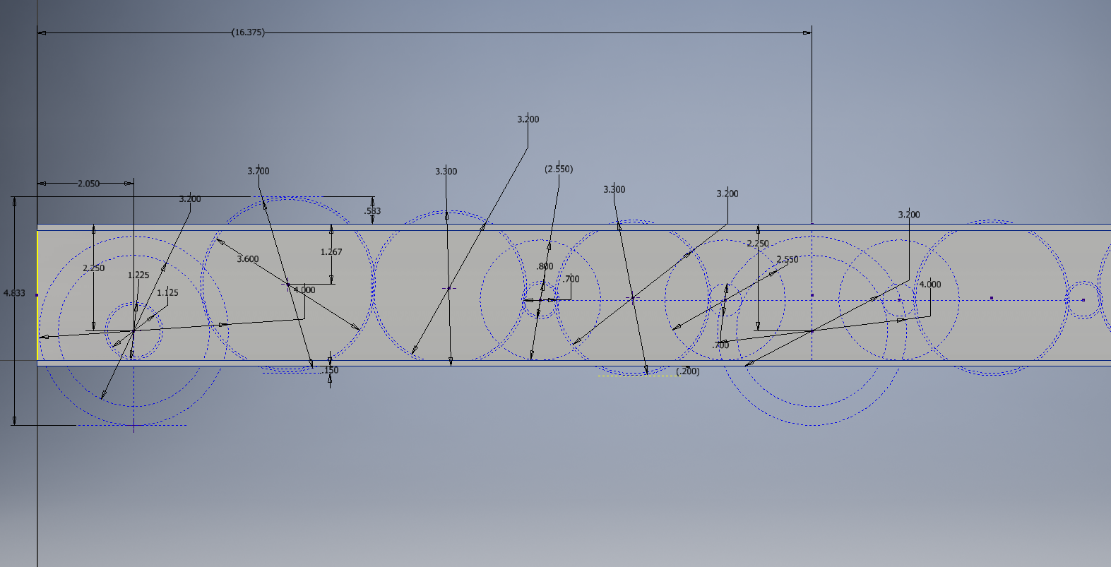
- Top of Drive Base is currently at 4.25 inches with total gear clearance at 4.83 inches. This is correcting the note that said the top was at 4.5 inches!
- front rail at 4.5 inches from the front of the frame for cube collector mechansim.
- 1/16 - arm is connecting to rail across the front, cube intake is intending to attach in front of the arm connection, on the diagonal frame supports. (from integration 1/16)
- 6 cims on 40 amp Breakers
- Bumpers will be 2" off the ground and overall 7" up
6 wheels
- 4 omni wheels with 2 colsen center wheels
6 Colson wheels will be tested
gear actuated
- gear ratio: 14-64
frame
- TBD: See discussion above on robot constraints. Connection needs and support needs of other mechanisms. Top priorities from integration is to locate the battery. Will need to know the location of the cube manupulator pivot point.
Current
1/23/2018
Today the drive train sub team is working on fabrication of parts and working more on detailing our parts, members of the team assembled parts for further fabrication and packaged parts to be put on the drive train shelving unit. Other members of our team are working on further detailing and precision on the CAD drive train drawing.
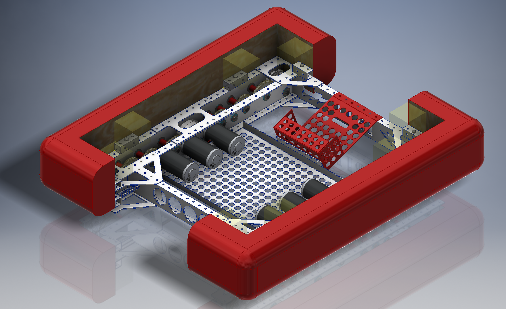
Working on developing cross supports. Discussion with cube intake group occurred today. Priority will be on starting the 3-d printing of the spacers. (completed 1/16) This is how our CAD assembly looks currently. Not all the way done; but it is almost there! Encoder selection completed on 1/16
Daily Journal Follows:
1/20/2018
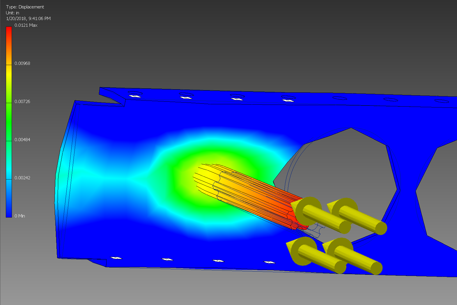
we can use one churro tube saving .125 pounds per side and still have a safty factor up to 1500lbs.
1/16/2018
Right now we are busy at work with finishing designs and drawings in CAD, Julia and Jordan are working on printing parts with the printer, and we added a few more items to the shopping list.
1/14/2018
Significant progress on frame. Front and back supports were designed. Discussion on placement of cube intake puts the inside of thefront rail at 4.5 inches from the front of the frame. Corner support brackets as well as the floor pan for supporting the batteries were put into CAD. Encoder Mount was designed. First parts were converted to part drawings. Roseanne had requested parts to go to Harris to see what level of support they could give. More stuff added to the shopping list.
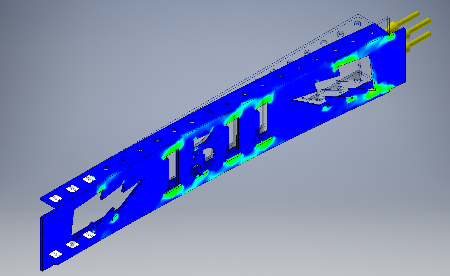
CAD is almost done and drawings have been started. Below is a picture of the cutout for the back brace of the robot with 2000 psi.
1/13/2018
CAD model of the gear and wheel assemblies are close to being completed and the development of the cross members has started. Waiting for first integration meeting to see what connection points will be requested by the cube management and robot lifting ramps will be needed.
Weights researched on 1/11/18 were used to update the CAD model to verify the weights developed in the CAD Model. 8 pm estimated weight is just under 34 lbs with cross connections still needed.
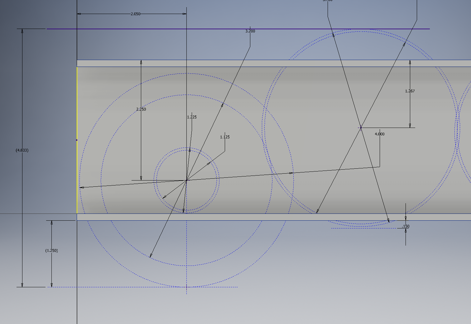
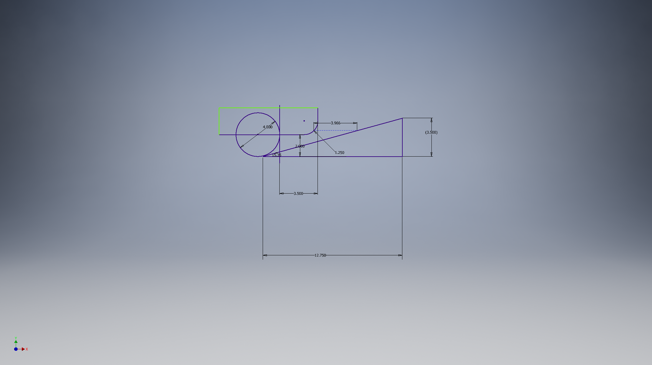
New sketch for key dimensions:
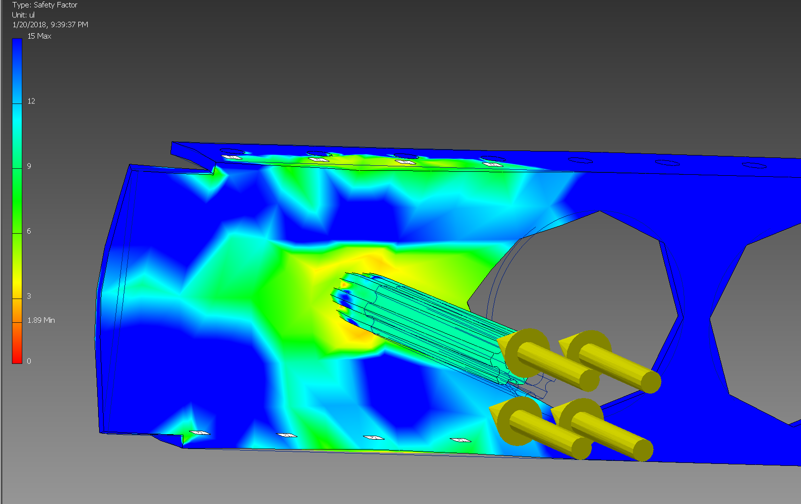
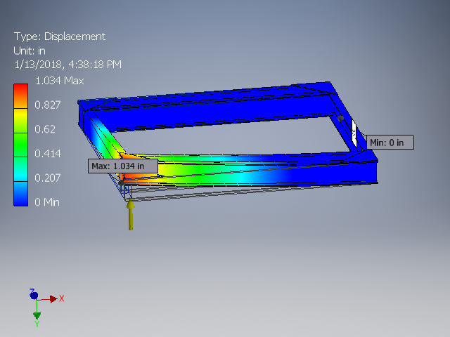
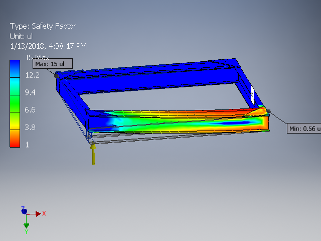
Mr Stoeckl did a finite element analysis (FEA) of the frame talking 1000 pound force from a bump and/or from a hit. This is the displacement:
And here is the image showing the safety factor:
1/11/2018
We determined the U-shaped rails, and ordered the material needed for it. Mentors had a late night discussion last night about the gears on the drive train, specificlly the idler gears and changing them from the 64 tooth to another size, as of now, a 72 tooth is in consideration. Plans for tonight are to work with CADing the drive base, as well as finalizing part orders. Our seconday goal is to get to work on a weight table. Below is all the dimensions you could possibly want and more for our drivetrain cad.
Weight Table created and added columns with information that will be handy when constructing the CAW (Cost Assessment Worksheet / a.k.a. BOM). Weight of gear and wheel assemblies is approx 33 lbs. This does not include cross braces and the plate planned for motor support.
1/10/2018
Design descisions: U shaped rails to support wheels, 4 omni and 2 colson, and a 14:64 gear ratio. Goal for tonight is to get a great start on the CAD model and identify things to go on the shopping list.
Ordering pocketed gears from west coast products.
1/7/2018
After the strategy discussion, we were told to keep defense in mind along with offense, after experimenting, strategy was reassured that the drivetrain would make it up the ramp and the robot would stay stable
After lunch we conducted tests with the 2017 and 2014 drive bases with the ramp and the conduit hump and determined that the 2017 drive base as is would not work however the 2014 drive base would due to ground clearances.
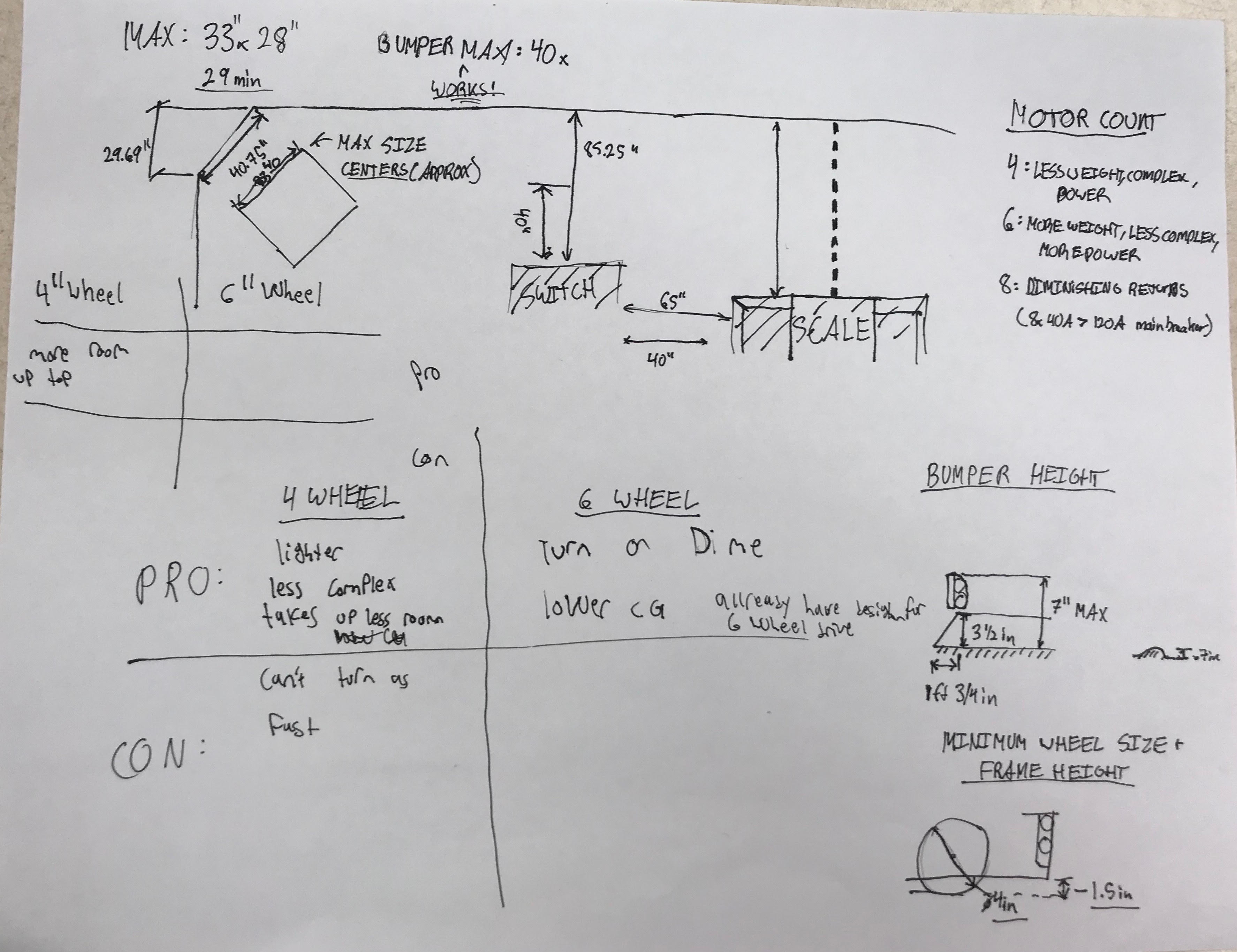
Concept study on wheel height on the platform. Verified that the base with 4 inch wheels will work on platform (included flat surface today to verify the position of the middle wheel). Also verified that the 6 inch wheel will be ok (bumper height needs to be 1.5" minimum).
modifications to the 2017 drive base to resolve previous issues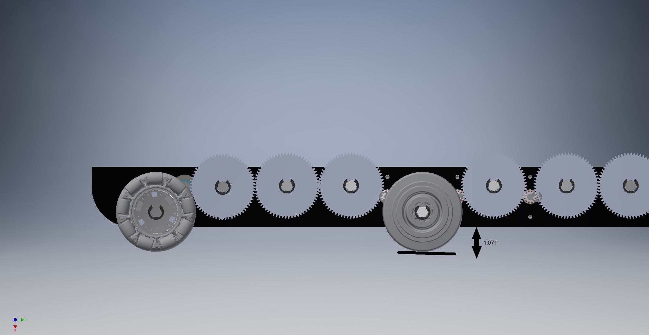
Shopping to check aluminum gear proces for Pocketed vs non-pocketed: West Coast Products offered a pocketed VexPro Gear. 64 tooth gear cost +$4 when pocketed by WCP. 0.183 lbs per gear reduction, all 18 gears would be 3.3 lb reduction and cost $72. Just doing the 6 gears with load will save 1.1 lbs and cost $24. We could put holes through the non loaded idler gears to get the weight reduction without adding the cost.
1/6/2018
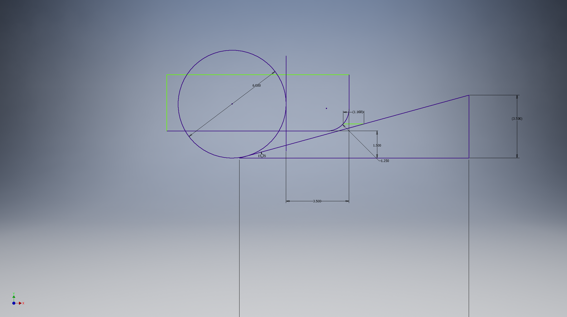
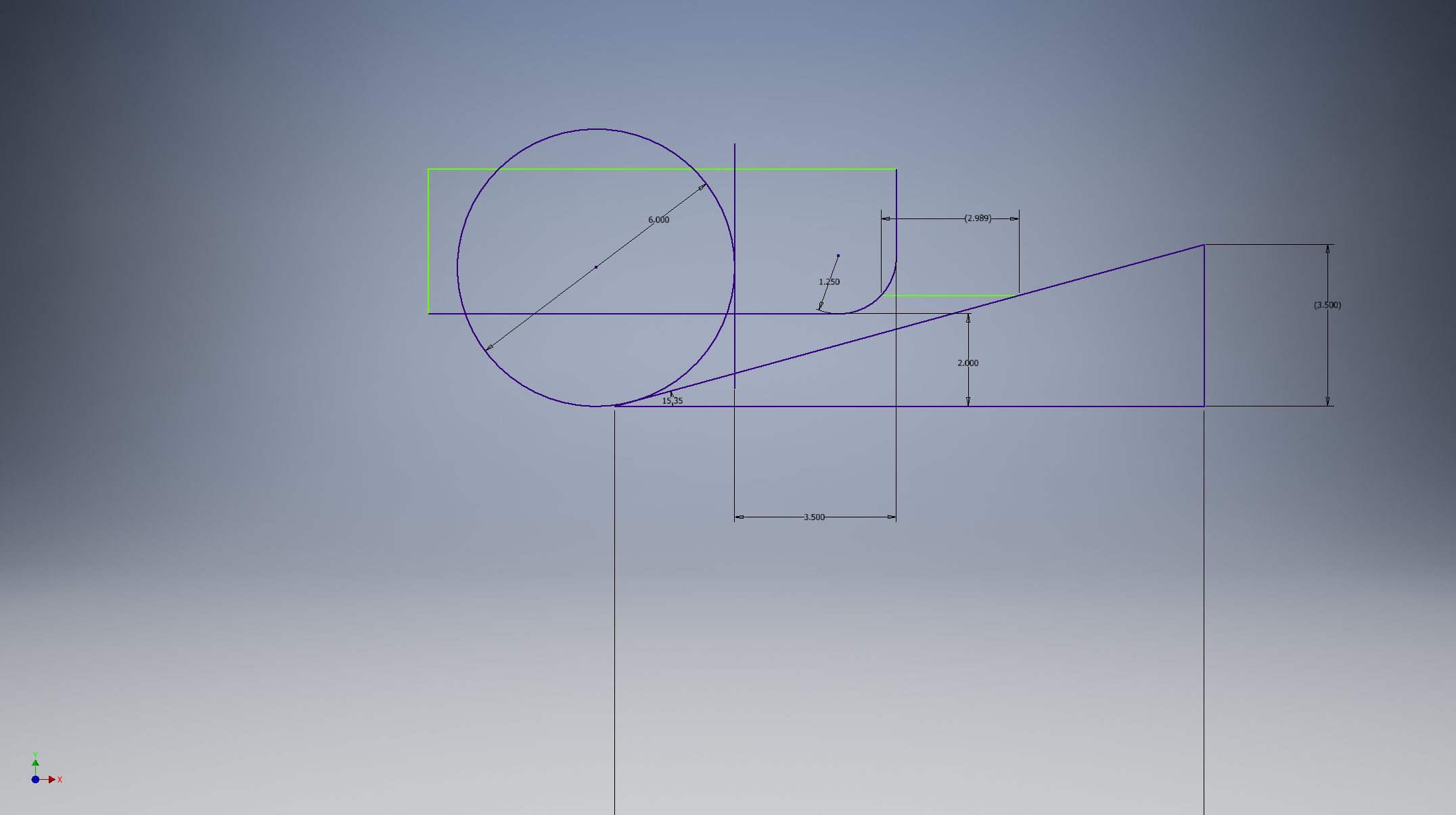
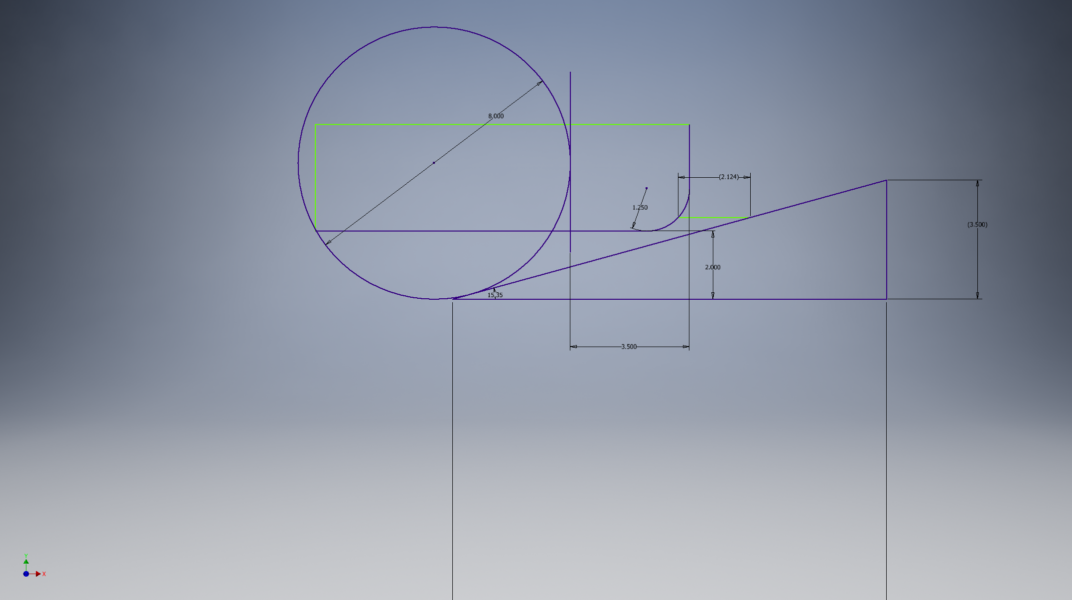
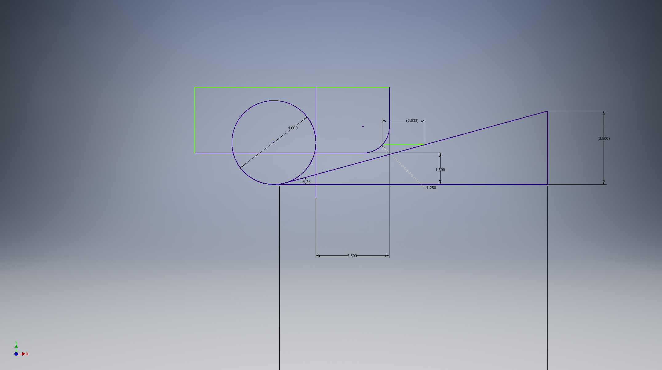
Made several drawings of different sized wheels and height of the bumpers; comparing it to the ramp.
4 inch wheels and 2 inch height
6 inch wheels 1.5 inch height
6 inch wheels 2 inch height
8 inch wheels 2 inch height
4 inch wheels 1.5 inch height
We could modify last year's drive base by changing the length, and the frame height from the ground. We can adapt it to any size based on what the other teams decide they want. This was the idea has been tested already last year and we know it is fast.
http://penfieldrobotics.com/wiki/images/6/69/A001_Final_Robot_Assembly_-_Larry.png
These are our notes comparing different size wheels and sizes of things on the field to possible drive train sizes.
