2009:Robot Design Details: Difference between revisions
From 1511Wookiee
Jump to navigationJump to search
No edit summary |
No edit summary |
||
| Line 51: | Line 51: | ||
*Two conveyors opposite each other, working together to move balls from ball intake and/or below the ball hopper up to the upper ball ejector/hopper entry point. | *Two conveyors opposite each other, working together to move balls from ball intake and/or below the ball hopper up to the upper ball ejector/hopper entry point. | ||
*Powered by two independent motors (XXX motors) | *Powered by two independent motors (XXX motors) | ||
*XXX sensor to detect ball "ready to shoot" at the top of the conveyor. | *XXX sensor to detect ball "ready to shoot" at the top of the conveyor. | ||
* | *Jaguar speed controller | ||
<br> | <br> | ||
== Upper Ball Ejector == | == Upper Ball Ejector == | ||
Revision as of 10:48, 10 January 2009
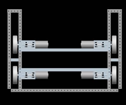
Drivetrain
- 4-wheel drive
- Banebots Transmissions
- 4 2.5" CIM motors
- Victor 884 [Drive] Speed Controllers
- Fixed wheels (slip-style steering)
- Banebots encoders on each wheel (http://banebots.com/pc/ELECTRONICS/EN-G0561-KT) -- mounted at transmission outputs.
- 27.25” LONG x 37.25” WIDE
- Rear wheel axis at 5.625 from most rear surfaces (adjustable down to 4.625 corner brace regime permitting)
- Front wheel axis at 11.625 from front most surfaces (adjustable ± 2.00”)
- Still need to determine a few hardware items but I think we could use a few PEM fasteners to further minimize fastener system weight
- We will need to design a few spacers “on the fly” as we determine the best approach while building
- The 6-hole patterns in the wheels need to be tapped for 10-32 Depth TBD
- Need to add the stiffener element between the wheels (1/side 1”x1” ext. Al stock is light and will work well and can be welded)
- Need to cut necessary smaller frame elements from stock
- Need to design in provisions for front “dummy wheels” biased 1/8” up for roll over protection
- Need to order the following parts from the shop by tomorrow (01/09/2009):
- 2009-wheel-hub (1/8 wheel retainer plate) QTY:4
- Hub-bearing (just a spacer in the hub for support not a bearing) QTY:4
- Brkt-wheel-asy-1 (trans/motor mount left front and right rear) QTY:2
- Brkt-wheel-asy-2 (trans/motor mount left rear and right front) QTY:2
- Bearing-block (main double bearing holder for each drive assembly) QTY:4
Lower Ball Collector
- Spinning "chicken pluckers" (?!?)
- Spins one way to take in/keep in ball, other way to eject them
- XXX motor
- XXX speed controller (or relay??)
Ball Hopper
- Open top entry for human player introduction
- Entry from conveyor at top of robot; entry controlled by upper ejector
- Exit is a "trap door" at the bottom of the hopper down to the area behind the lower ball collector and at the base of the conveyor system.
- Trap door powered by XXX motor (possibly a rack & pinion arrangement?)
- Two Limit Switches sensors to tell when door is in open/closed position
Ball Conveyor
- Two conveyors opposite each other, working together to move balls from ball intake and/or below the ball hopper up to the upper ball ejector/hopper entry point.
- Powered by two independent motors (XXX motors)
- XXX sensor to detect ball "ready to shoot" at the top of the conveyor.
- Jaguar speed controller
Upper Ball Ejector
- Spinning ejector directs, based on direction, balls out of robot or in to hopper entry point.
- XXX motor powered
- Jaguar speed controller
