2020:Hang
Team Leads: Alex F. & Nicole L.
| Pros | Cons | Pros | Cons |
|---|---|---|---|
| More Stable | Heavier | Lighter | Difficult to maintain |
| Fits within the allotted space better | Wider | Thinner | Having 2 hooks is harder |
| Easier to maintain | Harder to add self balancing mechanism | Easier to add self balancing mechanism | Less stability |
| Easier to have 2 hooks | Single motor | ||
| Single motor |
Explanation
- Pros of telescoping frame
- More stable
- Due to having 2 arms that are connected, it is going to be more stable than a single arm.
- Fits within allotted space better
- We have a lot of space side to side, but front to back we only have 1-7 inches max. Since each stage can be the same thickn ess as the other ones (since they don't have to fit inside each other), the first stages can be thinner than the ones of the telescoping arm.
- Easier to maintain
- Since the stages are next to each other, instead of inside each other, it will be much easier to fix between matches.
- Easier to have 2 hooks
- Since the frame will already have 2 sides, it will be very easy to put a hook on the top of each side of the third stage.
- Single motor
- Despite having two sides, the frame is still extended and retracted with a single winch in the middle of the two sides. Thereforem, it will only require a single motor (compared to a deplloyable hook which would likely require 2).
- More stable
- Cons of telescoping frame
- Heavier
- Since it has two sides, it will require more material than the telescoping arm, making it heavier.
- Wider
- The design has two sides, each of which will be three tubes of metal side by side. However, the telescoping arm will only require three total, which will be inside of each other.
- Harder to add self-orienting mechanism
- The self-orienting mechanism we protoyped really only works well with a single arm. It could be modified a bunch to work for two sides/a wider arm, or scaled up a bunch to work as it is.
- Heavier
- Pros of telescoping arm
- Lighter
- It's only a single arm, so it will require less material.
- Thinner
- The telescoping arm will only have 3 tubes of metal, with the last two being inside the first. Therefore, the mechanism will ony be as wide as the first stage (not including the winch).
- Easier to add self-orienting mechanism
- The self-orienting mechanism that we prototyped is designed to work with one arm, meaning that adding it to the end of the telscoping arm would not be too dificult (compared to the telescoping frame).
- Single motor
- This prototype also only requies a single motor, since it only has a single winch in the center.
- Lighter
- Cons of telescoping arm
- Less stable
- Since it would be a single arm anchored at a single point, it would be less stable and more prone to swinging around on the bar after climbing.
- Difficult to maintain
- Since the stages are inside each other, it would be much harder to repair between matches (see 2016).
- Harder to fit 2 hooks
- The center support in the middle of the bar is 3 inches wide. This makes a single telescoping arm with two hooks even less practical, as it requires the third (and thinnest) stage to be wide enough to fit 2 hooks with 3 inches in between. Stage 2 will then need to be even wider, and stage 1 will need to be even wider than stage 2. This means the telescoping arem would have to be very big to allow 2 hooks, adding more weight and potentially making it hharder to fit inside of the allotted 5 inches or so. This problem would be solved by putting the self orienting hook mechanism on the end though.
- Less stable
Prototyping 1/5/2020-1/11/2020
Overview: Based on initial team brainstorming and sketching, as well as the information from Strategy Subteam, we determined to prototype:
- Telescoping arm
- We are also prototyping a self-balancing mechanism.
- Deployed hook
- Hook designs
Observations: We observed the following over the course of prototyping:
- Both prototypes work well.
Decisions:
- We will either have a telescoping frame or a telescoping arm.
- We will not attach parallel to the bar, we want to come at it perpendicular (drive into it)
Need to do:
- Research COTS hooks, other hook designs
- Begin work on CAD designs for the arm and hook
- Decide on telescoping frame or telescoping arm.
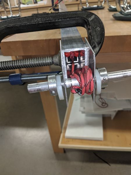
 Telescoping arm Winch prototype
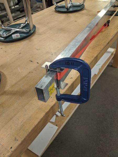
 Telescoping arm prototype other end
Design
Daily Diary
1/7/2020 5:00-9:00
Attendance: Alex F, Nate S, Nicole L, Elliot W, Nevin W, Michael N, Ben S
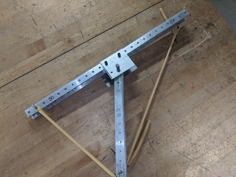
We re-tested the telescoping arm and designed a self orienting hook mechanism base. Tommorow, we have to finish that and adjust the surgical tubing and add hooks to the bar. We need the tape measure spring for the final telescoping arm design if we choose to follow that route (and need the actual hooks, which are being prototyped as we speak/type). We have to decide if we want 1 or 2 telescoping arms still, it depends. See robot design for pictures or will update later. Videos are not allowed, on this wiki, so more pictures.
1/8/2020 5:00-9:00
Attendance: Nicole, Alex F, Nate S, Trevor W, Ben and Christian Stoeckl
Nicole/Stoeckl: I did the calculations for where both robots would have to hang and how heavy they are to be balanced, the file is on the harris drive as "Torque for Hang NL". This spreadsheet doesn't account for only one robot to hang and doesn't take the 8 deg of allowance from being balanced. Tommorow we will have to fix that so that it can display when a robot is balanced at the center which can help us figure out if we need one arm or two arms. Tommorow we also need to figure out the force to lift the robot with one or two robots which will lead us to know what type of motors we might need. We also still need to figure out the size of the constant force spring to bring up the hook alone. We have to CAD up a scale sketch of the different arms (telescoping arm and the deploying arm at least) with it on top of the drive base so we can see how many sections we will actually need to have.
Everyone that isn't Christian/Nicole: We finished the prototype for the self deploying hook by adding a quick hook to the end. We also fixed the tensioning on the self orienting hook prototype, so that the bar is relatively perpendicular to the arm. We then tested it by having it extend, put the hook over the bar, and then retract, leaving the hook on the bar. In theory, if we had another string attached to the hook, we would then be able to winch it. We discussed the pros and cons of having multiple hooks and/or having multiple arms. We decided against coming at the bar parallel. We still need to make decisions on basically everything.
1/9/2020 5:00-9:00
Attendance: Nicole L, Alex F, Nate S, Nevin W, Ben and Christian Stoeckl
Everyone that isn't Christian/Nicole: We narrowed down the options for our endgame mechanism between a telescoping frame and a telescoping arm. We also made sketches in Inventor modeling the two mechanisms to size. We established that having a two stage telescoping arm would require an arm that starts right at the 45" height limit. We made a pro/con list for each of them to present on Saturday. We will need to start working on 3D CAD designs for the mechanism we choose Saturday.
Christian/Nicole: We fixed the previous spreadsheet for hang to include the 8 deg balance allowance, this is on the Harris Drive as "Torque for Hang NL" in the 3rd tab i believe. The concept of this spreadsheet is similar to the last with some new variables given that there is now a change on how the 8 deg will effect where you can balance given that the robots are spaced apart a changable distance and weigh a changeable weight. I also did calculations on how many times a winch would need to rotate given a changable diameter and changable height the robot needs to be lifted. I then calculated how quickly some motors we commonly use (CIMs, 775 pros, etc) would take the weight of the robot up to climb. The quickest time was for 1.3 seconds going about 70 rotations/sec (i think i dont have access to the spreadsheet right now). We also figured out the gear box ratio. The reason we did this was so that we know how many motors we need to lift the robot, whether or not that is with one arm or two, the lift mechanism will only need one motor, which helps possibly eliminate the worry about using up our motor count depending on our hook config. I think that is all the calculations and stoecklometry we needed to do to get a basic understanding of the requirements to lift and balance on the hanger, so now we just need to see how the robot design meeting goes.
nicole i deleted your stuff sorry :( (its ok i fixed it-NL :) )
1/10/2020 12:00-11:59
Attendance: Alex F
Alex F: Reformatted and added explanation for pro/con list.
Nicole L: Readded the entry that got mysteriously deleted by an unknown force
