2023:Drive Base
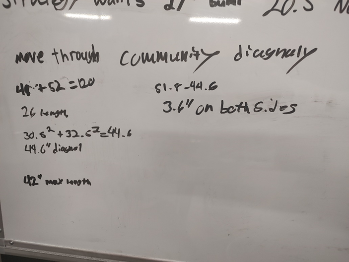
Calculations for the drive base perimeter and diagonal distance based on constraints from strategy and various subteam leads. Refer any questions to Nick L. or Berkeley P, class of 2023.
1/15/2023:
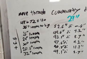
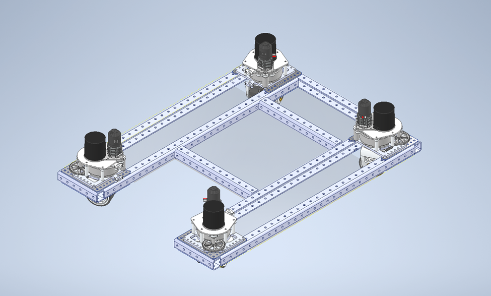
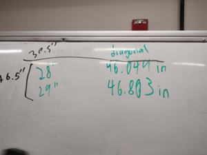
Based on our calculations, driver input, subteam and strategy requirements, and mentor approval, we first proposed to use a 26.25 inch by 30.25 inch drive base WITHOUT bumpers, and 32.75 inch by 36.75 inch WITH bumpers. This would allow us to have a diagonal of 49.225 inches, and a minimum extra distance of 6.775 inches while in the shortest part of the community. Additionally, a 12 inch by 10 inch square bumper cutout is necessary for intake.
1/17/2023:
Drive base length has changed to 32.25 inches, at the request of the Lift subteam (They wanted 38 or 36 to feel good, but this would make the robot HUGE). Additionally, we have explored the suggestion to make cutouts in the central C-channel and make the drive base width 2 inches smaller. We have a working CAD of this model, but with a cylinder representing the movement of the swerve modules, and the 2 inches of width removed.
1/19/2023:
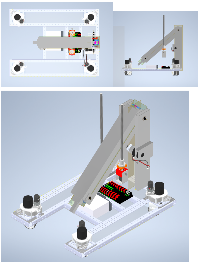
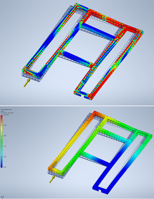
We made a final decision on drive base. The frame is 24.25 inches by 32.25 inches without bumpers. There will be cutouts on the inside c-channel to allow the swerve drives to be closer to the inside c-channel. This decision was unanimously voted for at the meeting on 1/19/2023, with both mentor and student approval. We determined that the smaller space would not hinder pit crew in removing the swerve modules if necessary, and that the swerve wheels can rotate freely. Additionally, an FEA analysis of the drive base does not show significant stress on the area where material will be removed for the cutout, and the lead mechanical mentor assured us that it would be structurally stable. This change makes the overall drive base smaller, and brings the diagonal distance to 49.468 inches, leaving us 6.5 inches under our maximum distance of 56 inches.
1/21/2023 (Approximately 5:00pm):
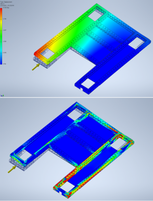
Made the FEA analysis shown in the 4 images. This shows the areas of greatest stress on the drive base, and shows the validation for the cutouts from 1/19's drive base decisions. Additionally, while the first pair of images shows a high amount of stress, the second pair of images has much less stress due to the addition of the Lexan bellypan. We also plan to explore additional diagonal brackets on the sides of the robot to improve stability. While the Lexan design is not finished (Additional lightening and attachment holes are needed), this demonstrates that the drive base will be more stable with these additions. Later today and tommorow we plan to prototype 4 cylinders that extend from the bottom of the drive base to anchor us to the charging station. We will attach these to the bottom of our 2022 robot, and test the design on a mockup charge station.
1/21/2023 (Approx. 8:15 pm):
Tested 4 cylinders on 2022 robot. We found that brick mode did most of the heavy lifting to keep the robot from moving while on flat ground. We tested on a smooth concrete floor.
1/22/2023 (~5:00 pm):
Tested 4 cylinders on the robot while on a ramp, while on Lexan material. This was much more effective, and lifted the robot a few inches off the ground. We have removed 3.25 inches of length from the Lexan bellypan to allow space for this mechanism if necessary.
1/24/2023:
After integration, we put bumper mounts in the CAD based on the bumper mounts on the 2022 robot. We put lightening holes in the bellypan Lexan, and built a mount for the parking brake. After stress testing the parking break mount with FEA and the part made of 0.5 inch aluminum. All four aluminum pieces weight 1.648 lbs
1/25/2023:
Too much snow, no robots :(
1/26/2023:
We have removed the lightening holes from the Lexan, as they only remove about 0.25 lbs. We made a battery box prototype that did not work because it was too big for the robot. We made a nicer battery box that fits and lifts straight out of the robot instead of sliding it out. The battery box is 8.25" x 7.25"
1/28/2023 + 1/29/2023:
Battery box broke, but we fixed it. Many changes were made to battery box height, width, depth, and mounting holes. We plan to mount it on the drive base at each of the four corners, and secure it with a strap. This strap will also serve as a way to lift the battery out of the box. We made a prototype of the parking break, and 3d printed a, "hockey puck" to mount on the bottom. This worked well, and stayed in its shape while under large amounts of force. Shop drawings were made for all drive base parts except those associated with the parking break. Lastly, the U-Brackets finally arrived! The drive base will be welded together and assembled by the next meeting.
