2018:End Game Mechanism
Subteam Leads: Mark M, Tai L, Rachel B
Current Design Information
- Things we need to document here:
- Any picture/sketch of the overall design would go a long way for understanding!
- How are the ramps held inside the robot starting config?
- How are they deployed (conceptually and mechanically - what actions or actuations??) Do cube mechanism parts need to be put in any specific state beforehand?
- How are they controlled once deployed? What's driving those scissor jacks/lifts?
- What is the range of travel on the scissor lift of the ramp?
- What happens if it goes too far?
- How do we know how far we've gone?
- Will the lifts back-drive under load of partner robots? If so, what holds them at position?
- What actuators are being used and what do they control??
Meeting Journal
Day 1>>>
Brainstormed concepts of how to climb:
Use climbing mechanism that will be able to share bar with another robot
Use climbing mechanism that will take up entire bar but will take another robot up with ours
Create our own ramp that will lift up both robots above 11"
Made sure our brainstormed designs would account for bumper rules ( We realized that prototypes that drop below our drivetrain violate the bumper rules. The bumper rule states
R24. BUMPERS must be located entirely within the BUMPER ZONE, which is the volume contained between the floor and a virtual horizontal plane 7 in. (~17 cm) above the floor in reference to the ROBOT standing normally on a flat floor. BUMPERS do not have to be parallel to the floor. This measurement is intended to be made as if the ROBOT is resting on a flat floor (without changing the ROBOT configuration), not relative to the height of the ROBOT from the FIELD carpet. Examples include: Example 2: A ROBOT deploys a MECHANISM which lifts the BUMPERS outside the BUMPER ZONE (when virtually transposed onto a flat floor). This violates R24) - Two ramps fold down, one end being fixed at around 11" above the platfrom and other end starting on the carpet, carpet end would raise up to around 11"
- Two ramps fold down, most of ramp is parallel and 11" above platform and at the end, it folds down at the same angle of the edge of the platform
- Same as first concept, except rather than having ramp start at carpet, it would start at the top edge of the platform
- Two ramps fold out like a butterfly (folds twice), first fold will have top of ramp at 11" above platform, would be 33" by 33", and second fold will extend down to the carpet where robots can drive up it
- Use a climbing mechanism that would take up entire bar but would be able to take another robot up with us
- Use a climbing mechanism that would be small enough to share bar with another robot
- Have bar on bottom of robot, would have another robtot connect on bottom after we are all the way up
Day 2>>>
Realized ramp idea would be safer than climbing up, especially with other robots
Designed several different concepts for a ramp
Tested measurements and variables for the ramp (Angle tests: 13 15 20 25,Tests were worst case scenarios with 4 inch omni wheels and bumpers with 1.5 inch clearance.)
Started to lean more towards building a ramp for other robots to drive up
Day 3>>>
Started building carboard prototypes
Started putting concepts on CAD
Realized that Null Zone will interefere with the ramp design (Continued evaluation of the game by strategy revealed that it is possible for an opponent to defend one of our partners from getting on our ramp. If the opponent is touching their null zone they would completely block access to that side of our ramp. Because of this Strategy has given us the following criteria. Ramps must be accessed by robots from the platform zone.)
Began to think of how we would actuate certain designs ( Thinking about using pneumatics, car jacks)
Day 4 >>>
Narrowed down to 2 ramp designs:
- One design had a side fixed at 11" with a hinge and the other side would rise up with some type of actuator
- The other design would have two plates flat on the platform that the robots would drive up on and then the plates would rise up like an elevator
Day 5 >>>
Started buildings design with foam core
Were able to find out final dimensions with drive team base
Finished CAD prototyping
Prepared speech for Saturday objective tables
-Develop best concept
Fit within space allowed
-Ability to be consistent
- Meet weight requirement
-Able to account for other teams robots
-That we can fit it into our own
-Buildible
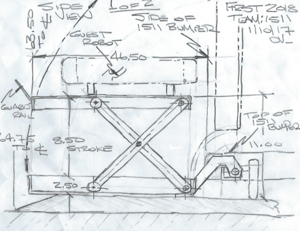
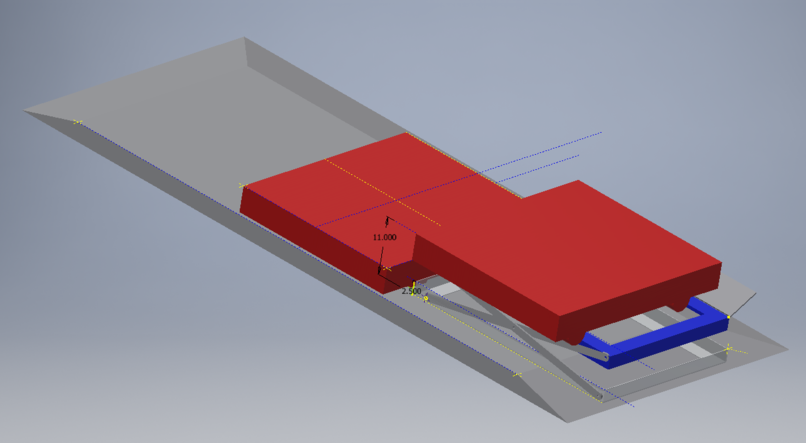
Lift Concept Side View
Check out the POC Video of this Concept on Day 7:
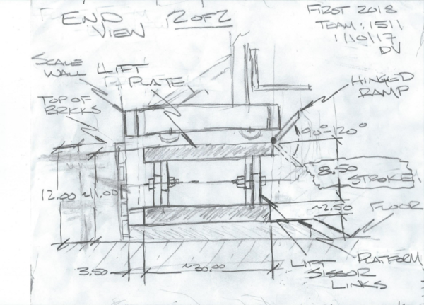
Lift Concept End View
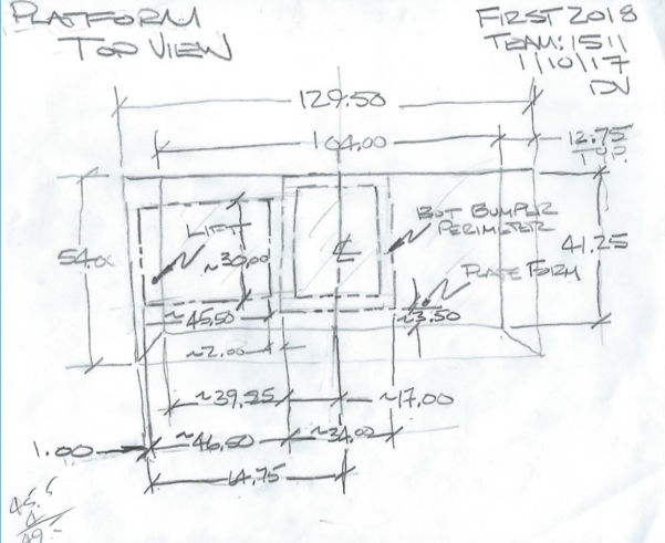
Lift Concept Plan View
Day 6>>>
Weighted objective tables for which mechanism we would use ( Either the elevator or the hinge)
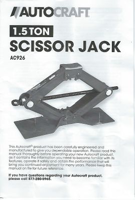
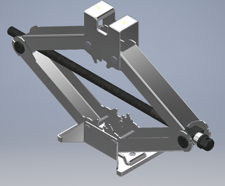
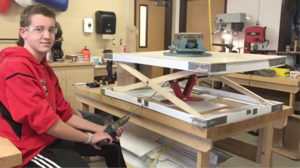
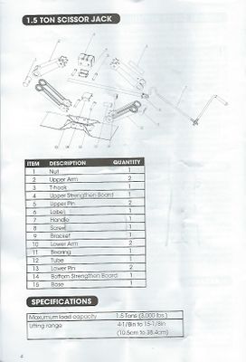
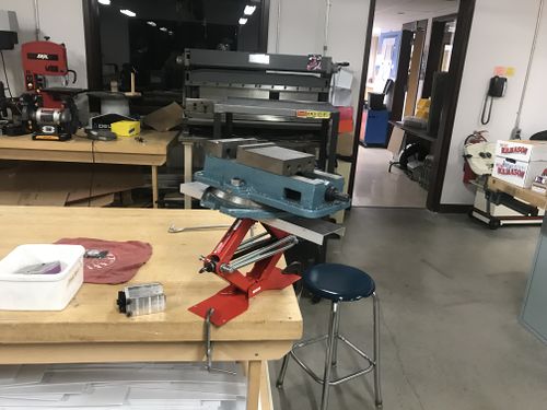
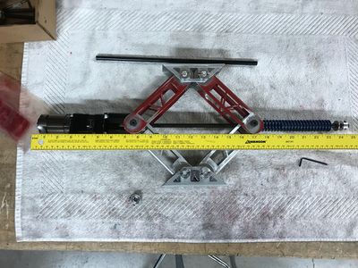
Look at possibly using a Sissors Jack Mechanism for the lift... obtained a AutoCraft AC926 Scissor Jack to experiment and analyze its capabilities.
CAD of our concept with actual measurements
Started to CAD the car jack for our lift
Day 7 (11/14/2018 )>>>
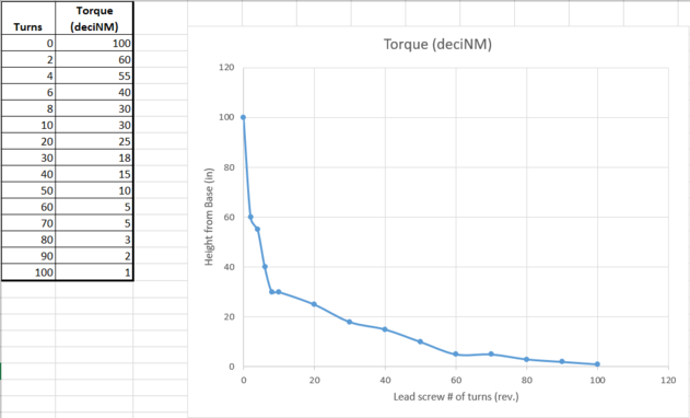
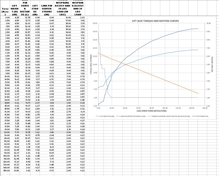
AC926 Scissor Jack Torque Curve
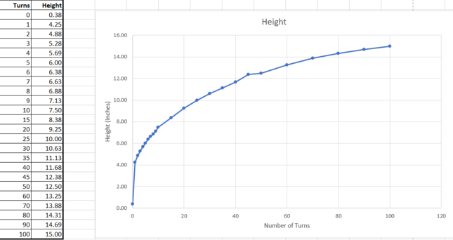
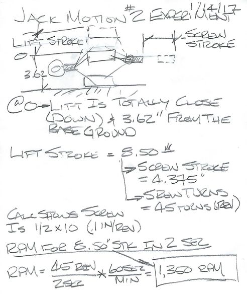
AC926 Scissor Jack Motion Curve
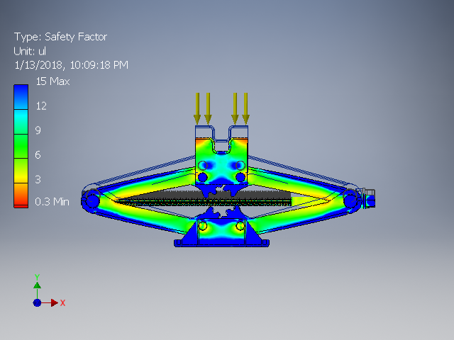
Aluminum Jack load analysis
Car jack can hold 650 lbs with 0.1 inches of deflection
This is the torque and motions curve for the final production model lift jack with a 35 pound lift load applied
1511 2018 Robot Lift POC Video
Click to View Video:Media:1511_2018_Robot_Lift_POC_Videp_01142018.zip
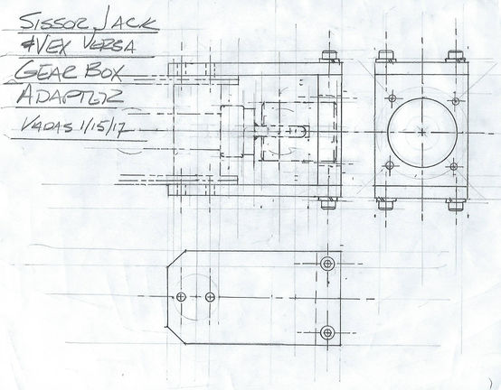
Potential Lift Drive Motor and Gear Box
Vex 775 Pro Motor: https://www.vexrobotics.com/versaplanetary.html
Vex Planetary Gear Box: https://www.vexrobotics.com/217-4347.html
Vex 775 Pro Motor Spec:http://motors.vex.com/vexpro-motors/775pro
POC Adapter
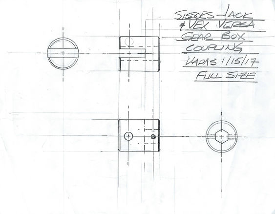
POC Coupling
POC AC926 Jack
AC926 Jack Motion Analysis
Day 8
-Springloading the car jack
-Making part files for each part of the car jack
- Began making Harris shop drawings tor car jack parts
Day 9
-Working on scissor jack assembly in CAD
-Tapping holes on car jack to allow for better spring loading
-
1/21/2018
-Weighed lead screw for jack. They weigh 0.9 lbs.
1/31/2018
https://photos.app.goo.gl/ToQFIZLOpAJ6nvlt1 To view the jack test click the link.
Overall Ramp: 36" x 25.375" x 2
Overall Ramp (ft): 3' x 2.114' x 2
Overall Area (ft): 12.684'
1/4" Thickness Weight: 0.79 lb/ft2
1/2" Thickness Weight: 0.84 lb/ft2
3/4" Thickness Weight: 0.94 lb/ft2
1/4" Overall Weight (lbs): 10.020 lbs
1/2" Overall Weight (lbs): 10.654 lbs
3/4" Overall Weight (lbs): 11.922 lbs
1/4" Overall Weight Actual with cutouts (lbs): 7.84312 lbs
2/14/2018 - Valentines Day
Production Lift Jack Serial Number LJ02 - Total Weight 4.61 Lbs.
This is not what our lifts actually look like
Tons of usefull reference links below>>>
putting together a 14-1 gear ratio motor:
http://www.flexicraft.com/Rubber_Expansion_Joints
http://www.enidine.com/en-US/Products/AirSprings/
R10LAM&ust=1515646785440859
https://www.enerpac.com/en/news/new-ultra-flat-hydraulic-cylinders
http://www.ergo-help.net/telescoping-air-cylinders.html
https://grabcad.com/library/manual-mini-scissor-lift-1
https://grabcad.com/naren-15/projects
2010 Breakaway
Team 118 Robonauts
https://youtu.be/PtRewwr59d8 - Team 118's robot for the 2014 FIRST Robotics Competition
https://youtu.be/sWHwDfpeYjo - firing winch hanger
https://youtu.be/sWHwDfpeYjo - Extending grabbing arm
FRC Team #971 Spartan Robotics
https://youtu.be/F_Auxy_ZdAQ - Good vertical lift FRC Team #971 Spartan Robotics
Cheif Delphi - How will your robot hand
https://www.chiefdelphi.com/forums/showthread.php?threadid=161014
https://www.onlinemetals.com/merchant.cfm?id=62&step=2&top_cat=60
https://www.plascore.com/honeycomb/honeycomb-panels/standard-honeycomb-panels/