2010:Robot Design Details
2010 Main Robot Design
- Thunderfoot kicker
- Thrasher bar for ball control
- Cable winch system
- Four wheel independent drive train
CURRENT TOTAL WEIGHT ESTIMATE: 120lbs
Drivetrain Design
- 4 Direct Drive CIM Motors
- 16:1 Banebots Transmissions
- 2 Traction Wheels in the Front
- 2 Omni Wheels in the back
Main Goals:
- Be able to go over the bumps
- Be manueverable
- Keep Balls from going underneath the robot
WEIGHT ESTIMATE: 50lbs
Mechanical 1 Design - Lift & Structure
- Using a mechanical 4 section telescope driven by pushing a cable up a tube to lift a hook
- Designed to lift the robot from either side off of the bump
- Has a pivoting mechanism that angles the telescope to the left or right depending on which side of the tower the robot is on
- Hook has a shepards crook design to be able to easily grab the high bar
- Winch pulls the telescoping tube back towards the robot to lift the robot off the ground
- Should be able to lift above needed height in under 5 seconds
- Using 1 CIM Motor,
Main Goals:
- Lift Robot above platform height as fast as possible (faster than 5 seconds)
- Extend lift and capture bar in under 5 seconds.
- Create an upper structure that supports the lift mechanism
- Create an upper structure that deflects balls
- Create an upper structure that potentially deflects balls towards the front of the robot
WEIGHT ESTIMATE: (tbd)lbs
Alternate Lifter Design for Possible Retrofit (3.8.10)
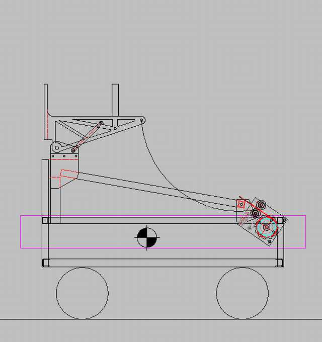
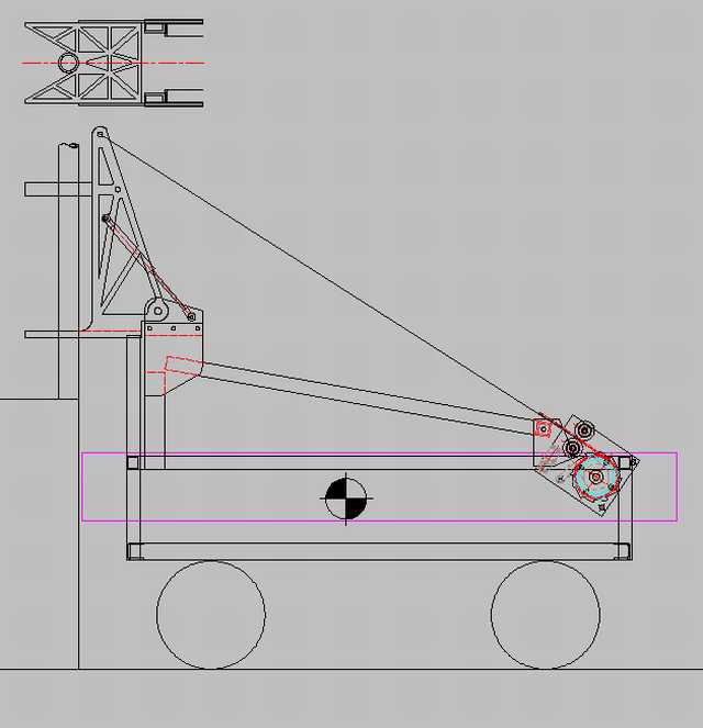
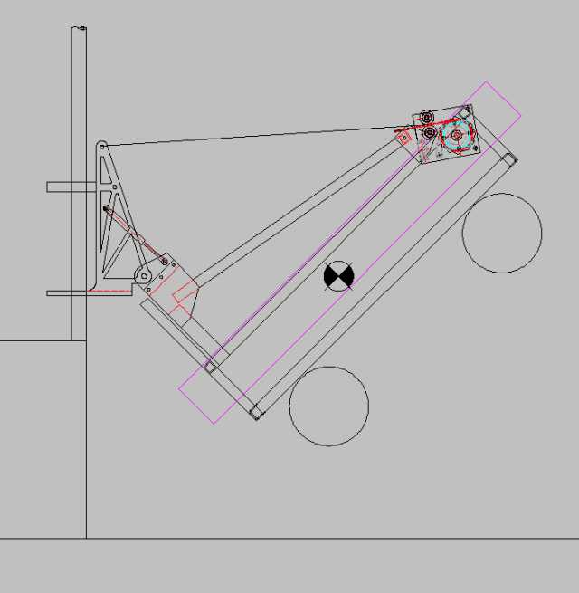
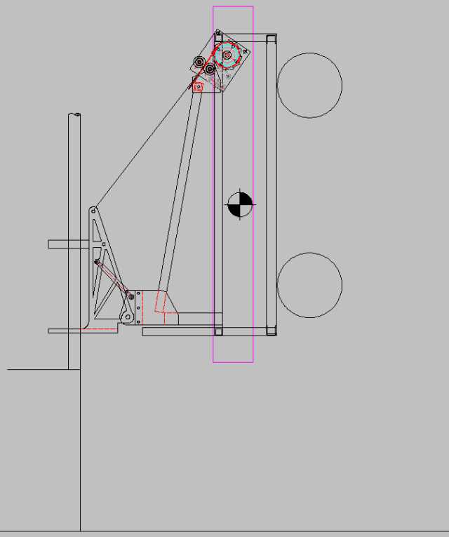
Pole grabber type lifter, which engages one of the two vertical poles from the floor, then folds to raise the robot to clear the tunnel. The original (telescopic) winch is reused, with only minor modifications, and is mounted via an adapter pad on the rear of the kicker structure. The folding grabber structure is mounted to the heavy front structure, with virtually no modification. A gas spring is used to rotate the grabber into position, and the grabber is held down during regular game play with a mechanical latch. A single servo motor is used to release the latch at the beginning of the 20 second finale period. The winch wire rope is stored in a slack state, and no winch movement is used to rotate the grabber into position. The ratchet pawl release servo is not used, as the ratchet remains in effect always, with spring application to augment gravity.
Normal Game Play Configuration
Pole Grabber In Position and Latched Onto Pole
Top view shows lower reaction plate detail - latch mechanism not yet sketched.
Folding In-Process
Folding Process Completed
Additional Thoughts:
1) The servo latch release can be eliminated by using the winch to hold the grabber in game play position, and paying out rope to allow the grabber structure to tilt into the finale position. The existing potentiometer is probably adequate for position input to the controls, but limit switches would be easy to add for backup.
2) An indicator light facing forward (towards the drive team) could be used to give positive indication that the gate latch has completely closed around the pole. Consider using control logic to 'set' the controls when the gate latch opens from the pole being driven through it, then lighting the indicator when it's fully closed - prevents the indicator from burning always. An alternative would be to use winch state (fully or nearly fully payed out to enable the light), instead of a microswitch at the gate latch.
3) Winch line pull would be reduced to approximately 125 lb (down from around 180+ lb when near the top of the climb with the telescopic system, due to friction and geometry), and two parts of line would be required to get the ~250 lb of total force at the grabber pin connection.
4) Winch speed would be increased due to reduced load, and the total amount of rope that needs to be spooled onto the winch is almost exactly the same as before. Total time to winch should therefore be decreased. Total cycle time (stand the grabber up, latch the pole, fold the bot) sho
5) A small wire rope block would be used at the top of the grabber structure, which could be marine type (for wire rope), or fabricated.
6) Total cycle time - stand the grabber up, latch the pole, fold the 'bot - should be somewhat less than with the telescopic style, and it should be considerably easier for the drive team to prep the climber and engage the pole. Once it's latched to the pole, it cannot be removed without direct human intervention, like coupling railroad cars, so once the pole is engaged by driving directly into it, the climb/fold operation is nearly fool-proof.
7) The existing superstructure would need to be removed from above the bumpers, and a substitute 'tent' system used to protect the internals and to shed balls.
8) The camera may be able to be put back on, in the space under and inside the grabber structure.
9) Total weight is expected (at this point) to be somewhat less than it is now, due mostly to the removal of the upper superstructure and window motor tilting mechanism.
Mechanical 2 Design - Kicker & Beater Bar
- Using 2 window motors and an electromagnet release
- Uses a "thunderfoot" kicker springloaded with surgical tubing to kick the ball
- Kicker will have variable positioning to kick ball different distances
- Beater bar is a simple spinning bar in the front of the robot that just spins to pull the balls into the robot and hold them while turning
Main Goals:
- Be able to kick the ball at distances from all 3 locations on the field (near, middle, far)
- Be able to score the ball when in the near zone
- Be able to control/possess balls while driving around the field
WEIGHT ESTIMATE: 30lbs
Electrical System
- 7 Jaguar Speed Controllers (main drive motors, lifting arm winch, lifting arm tilt, front thrasher)
- Power Distribution Board
- 120 amp Circuit Breaker
- Digital I/O sidecar
- Linksys Router
- 4 Spike Relays (2 for kicker motors, 2 electromagnets)
- cRIO (1 analog module, 1 digital modules) with 1 Digital Side Car
- Indicator Light
- Camera & mount (just tilt servo)
- Wires
- Magic
Main Goals:
- To Give all mechanical components power
- To give sensor readbacks that programming and operators need
- Make sure that the magic smoke that makes up all electrical components does not escape
WEIGHT ESTIMATE: 13 lbs
Motors List
- 4 CIM Motors - Drivetrain, driven by 4 Jaguars
- 1 CIM Motor - Lifter: Winch & Pushing cable, driven by Jaguar
- 1 Window Motor - Pivoting Mechanism, driven by Jaguar
- 2 Window Motors - Kicker, driven by 2 spike relays (maybe Victors)
- 1 Fisher Price Motor - Thrasher, driven by Jaguar
- 1 Camera Servo
- 1 Locking Servo for telescopic arm
Remaining Motors
- 1 Fisher Price, 1 Window motor, and 2 Mabuchi motors remaining
Sensors List
- 4 Banebots Encoders - Drivetrain
- 1 magnetic rotation sensor - Determine relative posistion of kicker pull back mechanism
- 1 BeamBreak Sensor - Ball Kicker
- 2 limit switches for kicker motors
- 1 photoreflective sensir for electromagnet contacting kicker
- Gyro
- Camera
- 1 analog sensor - winch for lift
- 1 limit switch for lift (max retract)
Autonomous Modes
0. Do nothing
- Near Zone: score 1 ball with dead reckoning
- ball placed in corner of 9x9 grid near goal
- robot placed against bump and angled to create straight line between it, the ball and the goal
- move to ball, move ball closer to goal (if needed), kick ball into goal, backup out of the way
- Near Zone: score 1 ball with camera guidance
- ball placed in corner of 9x9 grid near goal
- robot placed against bump and angled to create straight line between it, the ball and the goal
- move to ball, move ball closer to goal (if needed), align with target, kick ball into goal, backup out of the way
- Near Zone: score 1 ball with camera guidance and look for more balls
- same as "Near Zone: score 1 ball with camera guidance"
- search for more balls: pivot right and left looking for ball, drive to ball, align with target, kick ball into goal, backup
- Middle Zone: score 2 balls with dead reckoning
- ball 1 placed in corner of 9x9 grid near bump & center line
- ball 2 placed in center
- robot placed against bump and angled to create straight line between it, ball 1 and the goal
- move to ball 1, kick ball 1, turn towards ball 2, move to ball 2, turn back towards goal, kick ball 2, backup out of the way
- Middle Zone: score 2 balls with camera guidance
- ball 1 placed in corner of 9x9 grid near bump & center line
- ball 2 placed in center
- robot placed against bump and angled to create straight line between it, ball 1 and the goal
- move to ball 1, align with target, kick ball 1, turn towards ball 2, move to ball 2, align with target, kick ball 2, backup out of the way
- Far Zone: kick 3 balls with dead reckoning
- balls placed along edge of field (in front of each other on 9x9)
- robot goes against ramp in front of goal, not angled, to create a straight line between it, all 3 balls and the goal
- move to ball 1, kick ball 1, move to ball 2, kick ball 2, move to ball 3, kick ball 3
In all cases:
- Will allow for a delayed start
- Tilt down camera prior to tele-op mode


