Fabrication
NEW PROCESS IN DEVELOPMENT FOR USE WITH ONSHAPE. PLEASE BE PATIENT!
How To Submit Parts for Fabrication at L3Harris, for the PHS Shop (Team Made), or for the PHS CNC (Team Made)
Follow the steps below for proper modeling and submittal of parts. It is critical to understand the type of part that is being made (sheet metal or machined) as this will dictate the model generation along with the types of files that will be required in order to physically make the part.
If you have any questions for parts going to L3Harris for manufacturing, please ask Amy Averill (amy.averill@L3harris.com).
Steps For Fabrication
- Determine if the part will be a sheet metal part, Machined (solid) part, or a 3-d printed part
- Sheetmetal Parts: flat parts with holes that go all the way through the material, and may get bent into a shape
- Machined Parts: (1) pieces with intricate surfaces made from a block of metal or plastic, square or rectangular tube. (2) pieces made with bar stock, tube stock, hex rods or churro tube that needs to be cut to length, and or other features added.
- 3-D printed parts: pieces designed to be manufactured using the 3-D printing process.
Open the year specific Parts and Assembly Log (in Teams Robot Design channel) – assign the next number and complete the associated columns of the log for the part design phase.
Design the part in OnShape and create a part drawing for it:
NOTE: If you need to rename the part in OnShape: in the Part Studio, right-click in instances panel, then select Rename.
NOTE: Be sure to follow the instructions carefully! Your part will be rejected and not made if you do not follow the instructions!
NOTE: Have all files checked by a mentor!
NOTE: OnShape Tips and TricksSheetmetal Parts:
- You must meet very specific requirements in the design of your part. Follow these steps Creating a Sheet Metal Part Drawing
Machined Parts (for our shop):
- Create your part
- Create a drawing following the instructions here: Creating a Part Drawing
Machined Parts (for our CNC):
- Create your part
- Create a drawing following the instructions here: Creating a Part Drawing
- TBD .stp
Machined Parts (for L3Harris):
- Create your part
- Create a drawing following the instructions here: Creating a Part Drawing
- Create a .PDF following the instructions here: Creating a .PDF of a part drawing
- Create a .STP file following the instructions here: Creating a .STP file
- Send your .STP file and .PDF to L3Harris using the instructions here: Sending Files to L3Harris
3D Printed Parts:
- Create your part
- Create a drawing following the instructions here: Creating a Part Drawing
- Create a .STL file for the 3D printer following the instructions here: Creating a .STL File
THE FOLLOWING ARE OLD STEPS, SO SKIP THEM
- You made the required files in the prior step!
- Sheetmetal Parts
- .pdf (old instructions)
- .dxf - Must be 2000LT (old instructions)
- Machined Parts
- You made the required files in the prior step!
- Update the Google Drive Part & Assembly log to indicate that the part has been sent to L3Harris for fabrication.
| Date Files Emailed | Requested Item (Filename) | Requestor | Parts Ordered By/Date | Quantity Per Robot | Received Date |
|---|
.
How To 3D Print Parts
Follow the steps below for proper modeling of 3D printed parts.
If you have any questions, please ask Dave.
Steps For 3D Printing (Detailed Instructions)
- Open the part file you want to 3D Print
- Do an Export --> CAD Format
- Change the Save As Type to STL Files (*STL)
- In the file Dialog press the Options... button.
- Make sure the Format is set to Binary.
- Set the Units pull down selector to mm.
- Set the Resolution to High.
- Leave everything else as default.
- Press the OK button.
- Back in the file dialog navigate to the location you want to save the file and update the file name. Put 3D printer files in ..\02 Build Season (ROBOT)\10 Shop Drawings\3D Printer.
- Press the Save button in the file dialog.
- Create a drawing of the part and put it in the shop binder.
- Uncheck the box for Export Colors
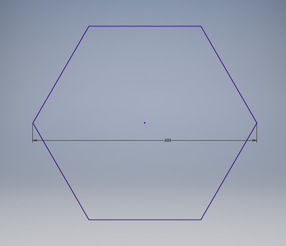
NOTE: The dimensions for a clearance hole for 1/2 inch hex axle is .60 inches from a corner of the hexagon to the opposite corner, as per photo below.
