Electrical: Difference between revisions
Mechanical1 (talk | contribs) No edit summary Tag: visualeditor-switched |
Programming (talk | contribs) No edit summary Tag: visualeditor |
||
| (3 intermediate revisions by 2 users not shown) | |||
| Line 1: | Line 1: | ||
==General Electrical Info:== | |||
<u>Terminating Wires:</u> | |||
For CAN: Green is Left/Ground, Yellow is Right | |||
For Power: Black is Left/Ground, Red is Right | |||
<u>Breakers(All should be in the MPT):</u> | |||
With PDH: | |||
20amp SnapAction | |||
30amp SnapAction | |||
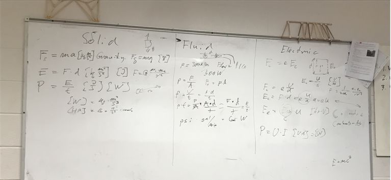
=== <u>Electrical Equations Explanation (Updated as of Nov 11th 2022)</u> | 40amp REV | ||
[[File:Electrical Eq.jpg]] | |||
<u>Pneumatics:</u> | |||
Green: Changing Pressures | |||
Yellow: High Pressure | |||
Blue: Low Pressure | |||
White: Extend | |||
Black: Retract | |||
==Electrical Wiring Diagrams: == | |||
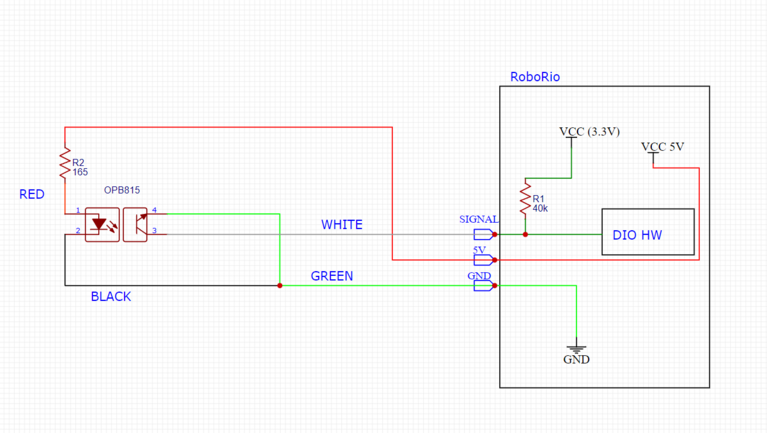
Optek Flag Sensor Wiring Diagram: | |||
[[File:Optek Flag Sensor Wiring Diagram.png|767x767px|link=https://wiki.penfieldrobotics.com/wiki/index.php%3Ftitle=File:Optek_Flag_Sensor_Wiring_Diagram.png]] | |||
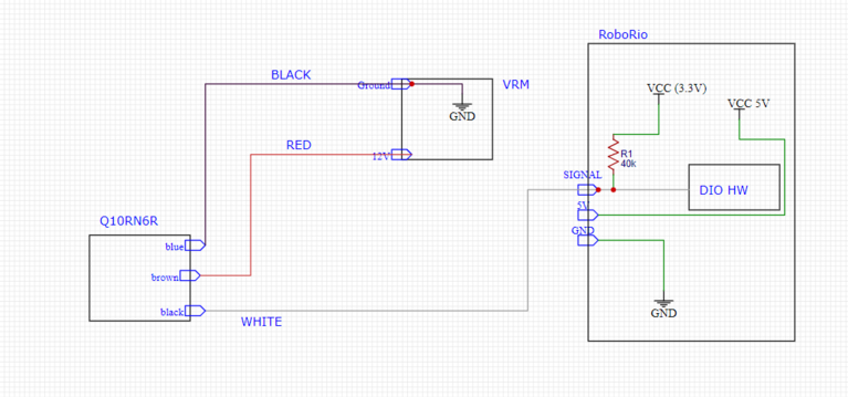
Q10 Series Banner Sensor Wiring Diagram: | |||
[[File:Q10 Series Banner Sensor Wiring Diagram.png|767x767px|link=https://wiki.penfieldrobotics.com/wiki/index.php%3Ftitle=File:Q10_Series_Banner_Sensor_Wiring_Diagram.png]] | |||
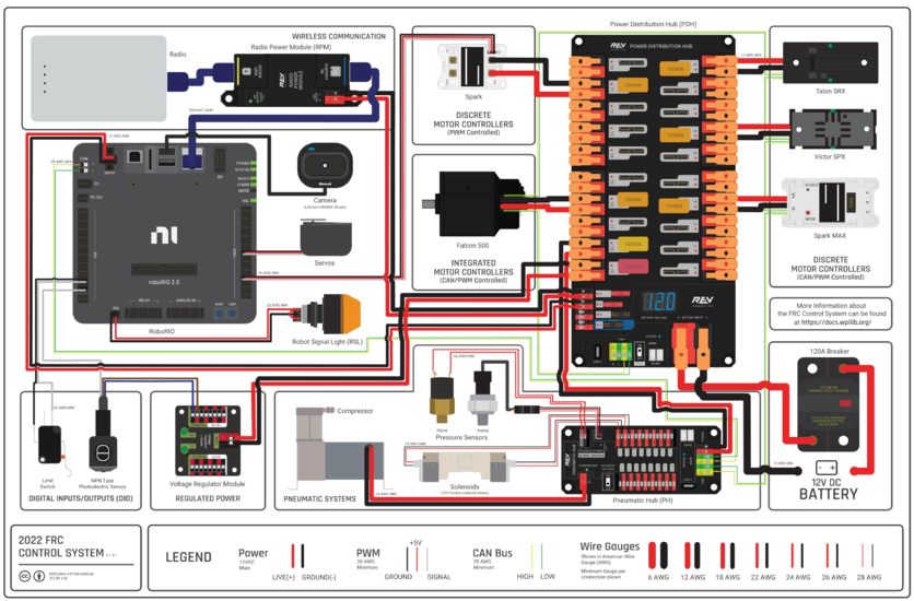
Wiring Diagram with Rev PDH | |||
[[File:PDH.png|836x836px|link=https://wiki.penfieldrobotics.com/wiki/index.php%3Ftitle=File:PDH.png]] | |||
==<u>Electrical Equations Explanation (Updated as of Nov 11th 2022)</u>== | |||
[[File:Electrical Eq.jpg|767x767px]] | |||
=====Solid===== | =====Solid===== | ||
| Line 68: | Line 95: | ||
C - Coulomb | C - Coulomb | ||
F<sub>e</sub> = e E<sub>e</sub> | F<sub>e</sub> = e E<sub>e</sub> | ||
Latest revision as of 06:14, 7 September 2023
General Electrical Info:
Terminating Wires:
For CAN: Green is Left/Ground, Yellow is Right
For Power: Black is Left/Ground, Red is Right
Breakers(All should be in the MPT):
With PDH:
20amp SnapAction
30amp SnapAction
40amp REV
Pneumatics:
Green: Changing Pressures
Yellow: High Pressure
Blue: Low Pressure
White: Extend
Black: Retract
Electrical Wiring Diagrams:
Optek Flag Sensor Wiring Diagram:
Q10 Series Banner Sensor Wiring Diagram:
Wiring Diagram with Rev PDH
Electrical Equations Explanation (Updated as of Nov 11th 2022)
Solid
F - Force (N)
m - Mass (kg)
a - Acceleration (m/s2)
g -Gravitational Acceleration
d - Distance
E - Electricity (J)
P - Power (W)
t - Time (sec)
Fg = ma
Fg = mg
E = F * d
P = E/t
Fluid
p - Pressure
f - Flow
A - Area
V - Volume
p = F/A
f = V/t = A*d/t
p * f = F/A * A*d/t = F*d/t = E/t
Electrical
U - Energy (V)
I - Current (Amps)
e - Charge of an Electron
C - Coulomb
Fe = e Ee
Ee = U/d
Fe = eU/d
Ee = Fd = eU/d * d = eU
C = (constant)*e
C = I*t
Ee = I *t * U
P = UI
Pneumatics Sources
- Fittings
- Air Tanks:
- Andymark - Clippard and unbranded seemingly similar to coastpneumatics products, $14-$17 for ~500ml
- Possible Solenoids - need closer review still:
- SMC SY3240-6 family - what we've always used in the past:
- Bimba / Pneumadyne
- NITRA from Automation Direct
- Mindman from Coast Pneumatics
- Andymark has Mead brand
- Explanation of various types of solenoids - they sell some too but they seem to be unsuitable for our application, but their explanation of how they work is pretty great!
- Relief Valve:
- Shut off valve
- Regulator:
- Andymark - Norgren kit recommended regulator, $28
- KleenRite has Norgren kit regulator for $17
Links and Resources


