2025:Controls: Difference between revisions
| (151 intermediate revisions by 3 users not shown) | |||
| Line 1: | Line 1: | ||
= New Rules = | = New Rules = | ||
*'''R907''' *No AC inverters. OPERATOR CONSOLES must not contain AC inverters. | *'''R907''' *No AC inverters. OPERATOR CONSOLES must not contain AC inverters. | ||
*The shelf also includes two clips to hold the shelf in place with a 1 in. (~25 mm) by 2 in. (~51 mm) thick tab that | *The shelf also includes two clips to hold the shelf in place with a 1 in. (~25 mm) by 2 in. (~51 mm) thick tab that | ||
= Overall Concept = | = Overall Concept = | ||
Dive Camera | <span style="font-size: 12pt;">'''https://wiki.penfieldrobotics.com/wiki/index.php?title=2026:Controls'''</span> | ||
<span style="font-size: 12pt;">'''Dive Camera'''</span> | |||
[[image: | <span style="font-size: 12pt;"></span>[[image:img1739157401435.jpeg|500px]] | ||
<span style="font-size: 12pt;"></span>[[image:img1739102339257.jpeg|500px]] | |||
[[image:img1738624351918.jpeg|500px]] | |||
[[image:img1738608815411.png|500px]] [[image:img1737924962407.png|500px]] | |||
[[image:img1736728545774.png|300px]] [[File:Thumbnail IMG 9638.jpg|300px]] [[File:Thumbnail IMG 9639.jpg|300px]] [[image:img1736648464356.png|300px]] | |||
Square Box (20" x 13.75"), One Handle on Each Side (8.5" Foam Grips ~1" round) | |||
Pop Off Lid | |||
Overall width: ~26" | |||
Handles: 8.5" Foam Grips (Trim Down Later) with round 1" and 1.5" by 3/4" square stock | |||
Lexan For Lens: 0.062 in Thick | |||
= Design Info = | |||
'''<span style="background-color: #ffffff; color: #e03e2d;">NOTE: laptop vent is on bottom of it, at back; so leave that area clear so air can flow out and go up the back of the box</span>''' | |||
Paint Scheme: | |||
*Bottom Box with Square stock metal - <span style="background-color: rgb(126, 140, 141);">Black</span> | |||
*Top - <span style="background-color: rgb(126, 140, 141);">Black</span> | |||
*End and top caps for handles - <span style="background-color: rgb(126, 140, 141);">Black</span> | |||
*Laptop stand - <span style="background-color: rgb(186, 55, 42);">Red</span> | |||
*Controller Holders - <span style="background-color: rgb(186, 55, 42);">Red</span> | |||
*Lens - <span style="background-color: #ba372a;">Red</span> | |||
Width considerations: | |||
*Should be less than 29.680in in Length due to the NEW Clips... clam shell may not be ideal | |||
*Try to get to box width to be 24" instead of initial 28" thought | |||
Use 'Giants of the Sea Font' from fontspace.com for cut outs. | |||
https://www.amazon.com/ | <p><span>[https://www.amazon.com/gp/product/B003VAHYQY/ref=ewc_pr_img_1?smid=ATVPDKIKX0DER&th=1 Controllers - Logitech]</span></p> | ||
:<span>Research options we did not use:</span> | |||
= | <li style="margin-left: 50px;"><span>[https://www.amazon.com/gp/product/B0CQP3LP3T/ref=ewc_pr_img_1?smid=A28DYDDFJA7HZ1&th=1 X-Box]</span></li> | ||
<li style="margin-left: 50px;"><span>[https://www.amazon.com/DIANVEN-Controller-Playstation-Windows-Vibration-4/dp/B0C9J8CT1H/ref=sr_1_1? Off-Brand PS]</span></li> | |||
<p><span>[https://www.thingiverse.com/thing:4566917 Controller Holder Starting Point]</span></p> | <p><span>[https://www.thingiverse.com/thing:4566917 Controller Holder Starting Point]</span></p> | ||
<p><span>[https://www.amazon.com/dp/B0C3H467SW/ref=sspa_dk_hqp_detail_aax_0?sp_csd=d2lkZ2V0TmFtZT1zcF9ocXBfc2hhcmVk&th=1 Magnet Latches]</span></p> | <p><span>[https://www.amazon.com/dp/B0C3H467SW/ref=sspa_dk_hqp_detail_aax_0?sp_csd=d2lkZ2V0TmFtZT1zcF9ocXBfc2hhcmVk&th=1 Magnet Latches]</span></p> | ||
| Line 58: | Line 63: | ||
<li style="margin-left: 50px;"><span>[https://www.walmart.com/ip/ROCKBROS-Bike-Handlebar-Grips-Foam-Comfortable-Shock-Absorption-Handle-Grips-for-BMX-Mountain-MTB-Beach-Cruiser-Scooter/1083117261?wmlspartner=wlpa&selectedSellerId=101072234&gQT=1 Bike Handlebar Grips]</span></li> | <li style="margin-left: 50px;"><span>[https://www.walmart.com/ip/ROCKBROS-Bike-Handlebar-Grips-Foam-Comfortable-Shock-Absorption-Handle-Grips-for-BMX-Mountain-MTB-Beach-Cruiser-Scooter/1083117261?wmlspartner=wlpa&selectedSellerId=101072234&gQT=1 Bike Handlebar Grips]</span></li> | ||
<li style="margin-left: 50px;"><span>[https://www.amazon.com/Grips-Foam-Drop-Comfort-Black/dp/B010U5SZ3I/ref=asc_df_B010U5SZ3I?mcid=1bdff52dc5f13e5f9e8d7fe64279526c&tag=hyprod-20&linkCode=df0&hvadid=693769151405&hvpos=&hvnetw=g&hvrand=17965477672384811053&hvpone=&hvptwo=&hvqmt=&hvdev=c&hvdvcmdl=&hvlocint=&hvlocphy=1022882&hvtargid=pla-903810009495&psc=1 Handlebar Foam]</span></li> | <li style="margin-left: 50px;"><span>[https://www.amazon.com/Grips-Foam-Drop-Comfort-Black/dp/B010U5SZ3I/ref=asc_df_B010U5SZ3I?mcid=1bdff52dc5f13e5f9e8d7fe64279526c&tag=hyprod-20&linkCode=df0&hvadid=693769151405&hvpos=&hvnetw=g&hvrand=17965477672384811053&hvpone=&hvptwo=&hvqmt=&hvdev=c&hvdvcmdl=&hvlocint=&hvlocphy=1022882&hvtargid=pla-903810009495&psc=1 Handlebar Foam]</span></li> | ||
<li style="margin-left: 50px;"><span>[https://www.amazon.com/uxcell-Tubing-Handle-Support-Insulation/dp/B0951YZXFD/ref=sr_1_8?crid=3JEFSBODLNAKI&dib=eyJ2IjoiMSJ9.-vR7mQZ3KeB55lLxmduXRsCCHmZ8lhWrEu8aKueW1WTQMvwt1oO2bOr-L2hrBZn6d2Ut5z43GZntkOyjs6okZ-w3OPG8PeEVgxTaXoSLLhJQfb2KDTpNX7Lun7nA0o9Ycc0Oh2UdeFZiGQ4xzAKTALpowgHGV2INBtm62ptnocMArchH7_4JQWVNE3JSr67X6XFCtYoOeeKG2z4uEaQCdGv3Coe8LWtwlWLZmu48Asdu7CO8ST6VQS8w59DoEUXywjwCRH6M1owPXs1MoKuUh7vwapPEGq-trQjdhZXqkT-Jk8wlzynBKsnygf2oVuRc5f-ZQOIQ0tKjsmtfRW_MExkletzLOFkIkK54U-irW-Q.t0TcIeOQGlBH9g8UFYmDECjHpS9uojPIEeJWA6K2zxw&dib_tag=se&keywords=uxcell+foam+tubing+25mmx35mm&qid=1736717182&s=hi&sprefix=uxcell+foam+tubbing+25mmx35mm%2Ctools%2C64&sr=1-8 Foam Tube]</span></li> | <li style="margin-left: 50px;"><span>[https://www.amazon.com/uxcell-Tubing-Handle-Support-Insulation/dp/B0951YZXFD/ref=sr_1_8?crid=3JEFSBODLNAKI&dib=eyJ2IjoiMSJ9.-vR7mQZ3KeB55lLxmduXRsCCHmZ8lhWrEu8aKueW1WTQMvwt1oO2bOr-L2hrBZn6d2Ut5z43GZntkOyjs6okZ-w3OPG8PeEVgxTaXoSLLhJQfb2KDTpNX7Lun7nA0o9Ycc0Oh2UdeFZiGQ4xzAKTALpowgHGV2INBtm62ptnocMArchH7_4JQWVNE3JSr67X6XFCtYoOeeKG2z4uEaQCdGv3Coe8LWtwlWLZmu48Asdu7CO8ST6VQS8w59DoEUXywjwCRH6M1owPXs1MoKuUh7vwapPEGq-trQjdhZXqkT-Jk8wlzynBKsnygf2oVuRc5f-ZQOIQ0tKjsmtfRW_MExkletzLOFkIkK54U-irW-Q.t0TcIeOQGlBH9g8UFYmDECjHpS9uojPIEeJWA6K2zxw&dib_tag=se&keywords=uxcell+foam+tubing+25mmx35mm&qid=1736717182&s=hi&sprefix=uxcell+foam+tubbing+25mmx35mm%2Ctools%2C64&sr=1-8 Foam Tube]</span><span></span></li> | ||
= To-Do = | = To-Do = | ||
| Line 65: | Line 70: | ||
== Completed == | == In Process == | ||
== <span style="background-color: rgb(248, 202, 198);"></span>Completed == | |||
*Confirmed for three Logitech controllers | *Beginning Steps | ||
*Collaborate and create ideas. Look at past Controls if needed. | ***Confirmed for three Logitech controllers | ||
*Take measures of computer and controllers being used. Look at 2024 Controls. | ***Collaborate and create ideas. Look at past Controls if needed. | ||
* | ***Take measures of computer and controllers being used. Look at 2024 Controls. | ||
*CAD/Assembly (in CAD) | |||
***Bottom Box | ***Bottom Box | ||
*****Increase height for controllers: 4.25" | *****Increase height for controllers: 4.25" | ||
| Line 104: | Line 92: | ||
*****Notches for the AC power and Ethernet bracket | *****Notches for the AC power and Ethernet bracket | ||
*****PEM holes for controller holders | *****PEM holes for controller holders | ||
*****fish font<br> | *****fish font | ||
*** | *****PEM Studs for magnets<br> | ||
***Laptop Holder/Broken Switches (may just need to update drawings) | *****Figure out what's broken with the controller holder assembly | ||
***ReCAD the laptop holder | *****Laptop Holder/Broken Switches (may just need to update drawings) | ||
***AC power and Ethernet bracket | *****ReCAD the laptop holder | ||
***Controller holder(s) | *****AC power and Ethernet bracket | ||
***Handles | *****Controller holder(s) | ||
*****Words in Laptop holder: DIVE | |||
*****Get controller spacing fixed | |||
*****Finalize length: 20" | |||
***Top <span style="background-color: rgb(241, 196, 15);">(thicker material .093)</span> | |||
*****Fill cut out in front <span style="background-color: rgb(241, 196, 15);">(Bend Radius: 0.032 in; Bend Reduction: -0.145)</span> | |||
*****Determine a method of keeping the top on the box - Will be doing the same method as Stronghold | |||
*******Find magnetic latches, get them on order. (Look in Design Info) | |||
*****Camera Lens (Holes for screws, Lexan) | |||
*****Camera grip/top opening (Holes for screws)<br> | |||
*****Flash (Holes for screws) | |||
*****Holes for Camera Lens in top | |||
*****Knob (Holes for screws, clicky thing) | |||
***Handles<br> | |||
*****Cap for the top of the handles | *****Cap for the top of the handles | ||
*****End cap for the bottom of the handles | *****End cap for the bottom of the handles | ||
*****Fixed/ Added to the Handle Assembly | *****Fixed/ Added to the Handle Assembly | ||
*** | *****Finalize design for handles<br> | ||
*Get | *****Top Caps - create whole for button mounting | ||
* | *Drawings | ||
* | ***Laptop Drawing | ||
*** | ***Top Drawing (and Submit) | ||
*Final Assembly | |||
***Picked paint scheme<br> | |||
***Found Parts: | |||
*****AC receptacle, AC cable, <span style="background-color: rgb(241, 196, 15);">RJ45 jack (NEEDS SOLDERED)</span>, broken switches, broken switch board, USB Hub, right angle USB adapters, Prototype Board, right angle Ethernet adapter | |||
*****label controllers | |||
***Order Parts: | |||
*****extension cord with multiple outlets, nano ardiuno | |||
***Reprint both handle Caps and Plugs in Red | |||
***Solder RJ45 Jack and Secure RJ45 Jack with approite secureness | |||
***Trim Wires on knob | |||
***Replace the termanel ends on broken switch things | |||
***Test broken switches<br> | |||
***Magents: | |||
*****Found Nuts | |||
*****Dremaled to Fit | |||
*****Used Lexan as spacers | |||
***Velcro controllers and their holders | |||
*<span style="background-color: #fbeeb8;">Painting </span>(3D pieces are '''<span>NOT</span>''' being painted): | |||
***<span style="background-color: #fbeeb8;">Black</span>: | |||
*****Top | |||
*****Bottom | |||
***<span style="background-color: #2dc26b;">Red</span>: | |||
*****Laptop Holder | |||
*<span style="background-color: #f1c40f;">While waiting for parts:</span><br> | |||
***<span style="background-color: #f8cac6;">Bits and Pieces:</span> | |||
*****Locknuts for PEM Studs (Eric is getting them at work... with some other things) | |||
*****Drill holes in tubes to fish wires through<br> | |||
*****Flash - Get plastic/lexan<br> | |||
*****Lens - Make lexan part | |||
***<span style="background-color: #f8cac6;">Wiring/Wire based:</span><br> | |||
*****Add Wires to LED buttons | |||
*<span style="background-color: #f1c40f;">While Test Fitting:</span> | |||
***<span style="background-color: #f8cac6;">Test Mounting:</span> | |||
****Knob, Magnets, Laptop + Controller Holders, Power/Ethernet, Buttons to Handles, Grip, Flash, Lens, Caps + Plugs | |||
***<span style="background-color: #f8cac6;">Bits and Pieces:</span> | |||
*****How many magnets will we be using??? | |||
*****Counter sink holes on top | |||
*****<span style="background-color: #f1c40f;">Final Assembly:</span> | |||
*******<span style="background-color: #f8cac6;">Bottom Box:</span> | |||
*********Velcro Laptop | |||
*********Mount Caps + Plugs, Laptop + Controller Holders | |||
*********<span style="background-color: #ffffff;">put on magnets on bottom; adjusting so top of top is flush/slight below bottom's edges</span> | |||
*********<span style="background-color: #ffffff;">put in broken switches</span> | |||
*********<span style="background-color: #ffffff;">Velcro broken switch board (under switches, right side) </span> | |||
*********<span style="background-color: #ffffff;">Velcro USB hub (flat side to bottom of case, ports facing towards side of case; just under right side of laptop; connect to USB on right side of laptop, using a right-angle USB)</span> | |||
*********<span style="background-color: #ffffff;">connect controller cables to USB hub (use cable tie mount to help it stay connected to hub)</span> | |||
*********<span style="background-color: #ffffff;">Velcro extension (side attached to bottom of case, plug facing under the laptop; just under left side of laptop)</span> | |||
*********<span style="background-color: #ffffff;">Velcro laptop power supply (under laptop; connect to extension cord)</span> | |||
*********<span style="background-color: #ffffff;">Velcro Arduino board</span> | |||
*********<span style="background-color: #ffffff;">Connect LEDs and handle switches to Arduino board</span><span style="background-color: #ffffff;"></span> | |||
*********put in Power, connect right angle network cable to it (connects to laptop)<span style="background-color: #ffffff;"></span> | |||
*********put in Ethernet, connect right angle network cable to it (connects to laptop) | |||
*********<span style="background-color: #ffffff;">Cable from Arduino to right side of laptop (use cable tie mount near board to help it stay connected; use right angle USB at laptop)</span><br> | |||
*********<span style="background-color: #ffffff;">cord mana<span style="text-decoration: underline;">g</span>ement</span><br> | |||
*********<span style="background-color: #ffffff;">USB Thumb drive extension cord</span> | |||
*********<span style="background-color: #ffffff;">Test Hub, control, controllers, and broken switches</span> | |||
*******<span style="background-color: #f8cac6;">Top Box:</span> | |||
*********Mount Grip, Flash, Knob, Lens<br> | |||
<li>Determined to put a hole through the top</li> | |||
<li>Determined to put epoxy and legos in lens</li> | |||
<li>placed legos in lens and expoyed it</li> | |||
<li>dremeled and sanded hole in top and touched up with tape</li> | |||
*<span style="background-color: #f8cac6;">Wiring:</span><br> | |||
***Make Arduino Board (see board layout below)<br> | |||
***Add connectors to handle switch wires<br> | |||
***[[image:img1738564713763.png|500px]]<br>NOTE: the diagram is the top view, so take that into consideration when wiring | |||
*<span style="background-color: #ffffff;" >Label broken switches</span> | |||
= Meeting Minutes = | = Meeting Minutes = | ||
| Line 170: | Line 238: | ||
<p>Attendees: Sami, Colin, Arlo, Byers, Eric, Charlie</p> | <p>Attendees: Sami, Colin, Arlo, Byers, Eric, Charlie</p> | ||
<p>Meeting Minutes:</p> | <p>Meeting Minutes:</p> | ||
<li> | <li>Redesigned Controller holder and test printed</li> | ||
<li>Put the handles in CAD</li> | <li>Put the handles in CAD</li> | ||
<p>'''1/15 (Wed)'''</p> | <p>'''1/15 (Wed)'''</p> | ||
| Line 217: | Line 285: | ||
***<span style="font-size: 14.4px;">finished magnet integration with other components</span> | ***<span style="font-size: 14.4px;">finished magnet integration with other components</span> | ||
<p>'''1/21 (Tue)'''</p> | <p>'''1/21 (Tue)'''</p> | ||
<p>Attendees: Sami, Colin, Arlo</p> | <p>Attendees: Sami, Colin, Arlo, Eric, Byers</p> | ||
<p>Meeting Minutes:</p> | <p>Meeting Minutes:</p> | ||
<li>Created/Refined more To - Do lists items</li> | <li>Created/Refined more To - Do lists items</li> | ||
< | <li>Cleaned up Wiki</li> | ||
< | <li>Created Laptop drawing and flat pattern for Harris</li> | ||
< | <li>Started items to put on top</li> | ||
<li>Updating the camera lens</li> | |||
<p>'''1/23 (Thu)'''</p> | <p>'''1/23 (Thu)'''</p> | ||
<p>Attendees: Colin,</p> | <p>Attendees: Sami, Colin, Byers</p> | ||
<p>Meeting Minutes:</p> | <p>Meeting Minutes:</p> | ||
<li>Controllers, grips, and magnetic latches received - Grips very bent :(</li> | |||
<li>Refined To - Do List</li> | |||
<li>Refined Lens - Made ledge for 0.062 in thick lexan</li> | |||
<li>Worked on Grip</li> | |||
<li>found bend radius and reduction for 0.093 in</li> | |||
<li>Started print for lens</li> | |||
<li>Picked some color schemes</li> | |||
<p>'''1/25 (Sat)'''</p> | <p>'''1/25 (Sat)'''</p> | ||
<p>Attendees:</p> | <p>Attendees: Sami, Arlo, Byers, Colin</p> | ||
<p>Meeting Minutes:</p> | <p>Meeting Minutes:</p> | ||
<li>Drilled holes in lens</li> | |||
<li>Fill cut out in front (Bend Radius: 0.032 in; Bend Reduction: -0.145)</li> | |||
<li>PEM Studs for magnets</li> | |||
<li>Top Caps - create whole for button mounting</li> | |||
<li>Flash</li> | |||
<li>Found Parts: AC receptacle, AC cable, RJ45 jack (NEEDS SOLDERED), broken switches, broken switch board, USB Hub, right angle USB adapters, Prototype Board, right angle Ethernet adapter</li> | |||
<li>Camera Lens (Holes for screws)</li> | |||
<li>Camera grip/top opening (Holes for screws)<br></li> | |||
<li>Flash (Holes for screws)</li> | |||
<li>Reprint both handle Caps and Plugs in Red</li> | |||
<li>Order Parts: extension cord with multiple outlets, Arduino Nano | |||
<p>'''1/26 (Sun)'''</p> | <p>'''1/26 (Sun)'''</p> | ||
<p>Attendees:</p> | <p>Attendees: Sami, Byers</p> | ||
<p>Meeting Minutes:</p> | <p>Meeting Minutes:</p></li> | ||
*Holes for Camera Lens in top | |||
*Knob (Holes for screws, clicky thing) | |||
*Top Drawing (and Submit) | |||
*Re - printed things from yesterday | |||
<p>'''1/28 (Tue)'''</p> | <p>'''1/28 (Tue)'''</p> | ||
<p>Attendees: Colin,</p> | <p>Attendees: Sami, Colin, Oliver, Charlie, Byers, Eric</p> | ||
<p>Meeting Minutes:</p> | <p>Meeting Minutes:</p> | ||
*Solder RJ45 Jack | |||
*Trim Wires on knob<br> | |||
*Replace the terminal ends on broken switch things | |||
*Test broken switches | |||
<p>'''1/29 (Wed)'''</p> | <p>'''1/29 (Wed)'''</p> | ||
<p>Attendees:</p> | <p>Attendees: Sami, Eric, Gracie</p> | ||
<p>Meeting Minutes:</p> | <p>Meeting Minutes:</p> | ||
*Fix and test broken switches | |||
*Secure RJ45 Jack with appropriate secureness | |||
*Found Nuts for Magnets | |||
*Velcro controllers and their holders | |||
<p>'''1/30 (Thu)'''</p> | <p>'''1/30 (Thu)'''</p> | ||
<p>Attendees: | <p>Attendees: Sami, Byers</p> | ||
<p>Meeting Minutes:</p> | <p>Meeting Minutes:</p> | ||
<li>Added terminals to extension cord, tested, and labeled</li> | |||
<li>Dremeled Magnets to Fit, Used Lexan as spacers for magnets<br></li> | |||
<p>'''2/1 (Sat)'''</p> | <p>'''2/1 (Sat)'''</p> | ||
<p>Attendees:</p> | <p>Attendees: Eric, Collin, Byers</p> | ||
<p>Meeting Minutes:</p> | <p>Meeting Minutes:</p> | ||
*parts came in | |||
*cut Lexan for lens | |||
*test fit all the parts: | |||
**cut PEM studs on top & bottom for magnets | |||
**controller was hitting front magnet, drilled holes in controller holders to shift them a little towards the back | |||
**filled sharp edges on bottom | |||
**counter sunk holes for top parts and bottom for controller holders | |||
**drilled holes in handle tubes for button wires | |||
*added a ground wire to the extension cord, and cut shrink wrap for it | |||
*determined all 4 magnets should be fine | |||
*discussed layout for Arduino board | |||
*painted parts (laptop tray, top & bottom) | |||
<p>'''2/2 (Sun)'''</p> | <p>'''2/2 (Sun)'''</p> | ||
<p>Attendees:</p> | <p>Attendees: Byers, Eric, Oliver</p> | ||
<p>Meeting Minutes:</p> | <p>Meeting Minutes:</p> | ||
*soldered wire to LEDs and double-sided taped them to the bottom | |||
*soldered wires to the handle buttons, mounted buttons, and ran wires through the handles | |||
*glued flash's clear part and the camera lens | |||
*determined general location for hub, power supply, extension cord, and Arduino board | |||
*mounted: | |||
**power plug, extension cord, heated shrink wrap, attached ground wire | |||
**laptop tray | |||
**magnet 'bars' on the top | |||
**controller holders | |||
**foam grips | |||
**handle caps and ends | |||
**camera lens | |||
**flash | |||
**top handle | |||
**clicky knob | |||
**Velcro to laptop tray and the laptop | |||
<p>'''2/4 (Tue)'''</p> | <p>'''2/4 (Tue)'''</p> | ||
<p>Attendees:</p> | <p>Attendees: Sami, Byers, Colin, Oliver, Arlo, Charlie</p> | ||
<p>Meeting Minutes:</p> | <p>Meeting Minutes:</p> | ||
*Make Arduino Board<br> | |||
*Add connectors to handle switch wires | |||
*<span style="background-color: #ffffff;">put on magnets on bottom; adjusting so top of top is flush/slight below bottom's edges</span> | |||
*<span style="background-color: #ffffff;">put in broken switches</span> | |||
*<span style="background-color: #ffffff;">Velcro broken switch board (under switches, right side) </span> | |||
*<span style="background-color: #ffffff;">Velcro USB hub (flat side to bottom of case, ports facing towards side of case; just under right side of laptop; connect to USB on right side of laptop, using a right-angle USB)</span> | |||
*<span style="background-color: #ffffff;">connect controller cables to USB hub (use cable tie mount to help it stay connected to hub)</span> | |||
*<span style="background-color: #ffffff;">Velcro extension (side attached to bottom of case, plug facing under the laptop; just under left side of laptop)</span> | |||
*<span style="background-color: #ffffff;">Velcro laptop power supply (under laptop; connect to extension cord)</span> | |||
*<span style="background-color: #ffffff;">Velcro Arduino board</span> | |||
*<span style="background-color: #ffffff;">Connect LEDs and handle switches to Arduino board</span><span style="background-color: #ffffff;"></span> | |||
*put in Power, connect right angle network cable to it (connects to laptop)<span style="background-color: #ffffff;"></span> | |||
<p>'''2/5 (Wed)'''</p> | <p>'''2/5 (Wed)'''</p> | ||
<p>Attendees:</p> | <p>Attendees: Sami, Eric</p> | ||
<p>Meeting Minutes:</p> | <p>Meeting Minutes:</p> | ||
*put in Ethernet, connect right angle network cable to it (connects to laptop) | |||
*<span style="background-color: #ffffff;">Cable from Arduino to right side of laptop (use cable tie mount near board to help it stay connected; use right angle USB at laptop)</span><br> | |||
*<span style="background-color: #ffffff;">cord mana<span style="text-decoration: underline;">g</span>ement</span><br> | |||
*<span style="background-color: #ffffff;">USB Thumb drive extension cord</span> | |||
*<span style="background-color: #ffffff;">Test Hub, control, controllers, and broken switches</span><br> | |||
<p>'''2/6 (Thu)'''</p> | <p>'''2/6 (Thu)'''</p> | ||
<p>Attendees:</p> | <p>Attendees: Collin, Byers</p> | ||
<p>Meeting Minutes:</p> | <p>Meeting Minutes:</p> | ||
*<span style="background-color: #ffffff;">labelled controllers</span> | |||
*<span style="background-color: #ffffff;">touched up silver screws (need to re-check once dry)</span> | |||
*<span style="background-color: #ffffff;">installed Arduino on the Controls laptop</span> | |||
<p>'''2/8 (Sat)'''</p> | <p>'''2/8 (Sat)'''</p> | ||
<p>Attendees: | <p>Attendees: Sami, Colin, Eric, Byers</p> | ||
<p>Meeting Minutes:</p> | <p>Meeting Minutes:</p> | ||
<li>Determined to put a hole through the top</li> | |||
<li>Determined to put epoxy and legos in lens</li> | |||
<li>placed legos in lens and expoyed it</li> | |||
<li>dremeled and sanded hole in top and touched up with tape<br></li> | |||
<li> | |||
<span style="background-color: #ffffff;">Found new power cord</span></li> | |||
<li> | |||
<span style="background-color: #ffffff;">Cleaned up lens and screwed on</span></li> | |||
<p>'''2/16 (Sat)'''</p> | <p>'''2/16 (Sat)'''</p> | ||
<p>Attendees: | <p>Attendees: Sami, Byers</p> | ||
<p>Meeting Minutes:</p> | <p>Meeting Minutes:</p> | ||
<li>Made new LED pattern (Finished)</li> | |||
<p>'''2/27 (Thu)'''</p> | <p>'''2/27 (Thu)'''</p> | ||
<p>Attendees: | <p>Attendees: Sami, Byers</p> | ||
<p>Meeting Minutes:</p> | <p>Meeting Minutes:</p> | ||
<li>Added Most recent Controller Map to page (from 2/27/2025 @ 17:33)</li> | |||
<li>Label broken switches</li> | |||
<p>'''3/19 (Wed)'''</p> | <p>'''3/19 (Wed)'''</p> | ||
<p>Attendees: | <p>Attendees: Averill</p> | ||
<p>Meeting Minutes:</p> | <p>Meeting Minutes:</p> | ||
<li>Verified the broken controller and replaced it.</li> | |||
<li>Put a replacement controller on the shopping list.</li> | |||
<li>Zip-tied the right angle connectors together.</li> | |||
<li>Verified stuff works.</li> | |||
= Controls Rules 2025 = | = Controls Rules 2025 = | ||
| Line 392: | Line 439: | ||
#be longer than 5 ft. (~152 cm), B. be deeper than 1 ft. 2 in. (~35 cm) (excluding any items that are held or worn by the DRIVERS<br>during the MATCH),<br>C. extend more than 6 ft. 6 in. (~198 cm) above the floor, or<br>D. attach to the FIELD (except via the loop tape as described in section 5.6.1 DRIVER STATIONS).<br>There is a 4 ft. 6 in. (~137 cm) long by 2 in. (nominal) wide strip of hook-and-loop<br>tape (“loop” side) along the center of the DRIVER STATION support shelf that<br>should be used to secure the OPERATOR CONSOLE to the shelf. See section<br>5.6.1 DRIVER STATIONS for details.<br>Please note that while there is no hard weight limit, OPERATOR CONSOLES that<br>weigh more than 30 lbs. (~13 kg.) will invite extra scrutiny as they are likely to<br>present unsafe circumstances. | #be longer than 5 ft. (~152 cm), B. be deeper than 1 ft. 2 in. (~35 cm) (excluding any items that are held or worn by the DRIVERS<br>during the MATCH),<br>C. extend more than 6 ft. 6 in. (~198 cm) above the floor, or<br>D. attach to the FIELD (except via the loop tape as described in section 5.6.1 DRIVER STATIONS).<br>There is a 4 ft. 6 in. (~137 cm) long by 2 in. (nominal) wide strip of hook-and-loop<br>tape (“loop” side) along the center of the DRIVER STATION support shelf that<br>should be used to secure the OPERATOR CONSOLE to the shelf. See section<br>5.6.1 DRIVER STATIONS for details.<br>Please note that while there is no hard weight limit, OPERATOR CONSOLES that<br>weigh more than 30 lbs. (~13 kg.) will invite extra scrutiny as they are likely to<br>present unsafe circumstances. | ||
*'''R907''' *No AC inverters. OPERATOR CONSOLES must not contain AC inverters | *'''R907''' *No AC inverters. OPERATOR CONSOLES must not contain AC inverters | ||
[[File:Screenshot 2025-01-05 195237.png|500px]] | |||
= 2025 Controller Map (From 2/27/2025 @ 17:33) = | |||
[[image:img1740775412945.png|500px]] | |||
= Archives = | = Archives = | ||
*[[2024:Controls]] | *[[2024:Controls]] | ||
Latest revision as of 14:26, 11 January 2026
New Rules
- R907 *No AC inverters. OPERATOR CONSOLES must not contain AC inverters.
- The shelf also includes two clips to hold the shelf in place with a 1 in. (~25 mm) by 2 in. (~51 mm) thick tab that
Overall Concept
https://wiki.penfieldrobotics.com/wiki/index.php?title=2026:Controls Dive Camera


Square Box (20" x 13.75"), One Handle on Each Side (8.5" Foam Grips ~1" round)
Pop Off Lid
Overall width: ~26"
Handles: 8.5" Foam Grips (Trim Down Later) with round 1" and 1.5" by 3/4" square stock
Lexan For Lens: 0.062 in Thick
Design Info
NOTE: laptop vent is on bottom of it, at back; so leave that area clear so air can flow out and go up the back of the box
Paint Scheme:
- Bottom Box with Square stock metal - Black
- Top - Black
- End and top caps for handles - Black
- Laptop stand - Red
- Controller Holders - Red
- Lens - Red
Width considerations:
- Should be less than 29.680in in Length due to the NEW Clips... clam shell may not be ideal
- Try to get to box width to be 24" instead of initial 28" thought
Use 'Giants of the Sea Font' from fontspace.com for cut outs.
- Research options we did not use:
Controller Holder Starting Point
How to make grips: drill hole in top half of square stock and inset the round 1" tube and have L3Harris model shop weld them together, then put foam over the round tube.
Research options we did not use:
To-Do
Not Started
In Process
Completed
- Beginning Steps
- Confirmed for three Logitech controllers
- Collaborate and create ideas. Look at past Controls if needed.
- Take measures of computer and controllers being used. Look at 2024 Controls.
- CAD/Assembly (in CAD)
- Bottom Box
- Increase height for controllers: 4.25"
- Add notch for keyboard cutout
- Square cutouts for the handles
- PEM holes for laptop holder
- Notches for the AC power and Ethernet bracket
- PEM holes for controller holders
- fish font
- PEM Studs for magnets
- Figure out what's broken with the controller holder assembly
- Laptop Holder/Broken Switches (may just need to update drawings)
- ReCAD the laptop holder
- AC power and Ethernet bracket
- Controller holder(s)
- Words in Laptop holder: DIVE
- Get controller spacing fixed
- Finalize length: 20"
- Top (thicker material .093)
- Fill cut out in front (Bend Radius: 0.032 in; Bend Reduction: -0.145)
- Determine a method of keeping the top on the box - Will be doing the same method as Stronghold
- Find magnetic latches, get them on order. (Look in Design Info)
- Camera Lens (Holes for screws, Lexan)
- Camera grip/top opening (Holes for screws)
- Flash (Holes for screws)
- Holes for Camera Lens in top
- Knob (Holes for screws, clicky thing)
- Handles
- Cap for the top of the handles
- End cap for the bottom of the handles
- Fixed/ Added to the Handle Assembly
- Finalize design for handles
- Top Caps - create whole for button mounting
- Bottom Box
- Drawings
- Laptop Drawing
- Top Drawing (and Submit)
- Final Assembly
- Picked paint scheme
- Found Parts:
- AC receptacle, AC cable, RJ45 jack (NEEDS SOLDERED), broken switches, broken switch board, USB Hub, right angle USB adapters, Prototype Board, right angle Ethernet adapter
- label controllers
- Order Parts:
- extension cord with multiple outlets, nano ardiuno
- Reprint both handle Caps and Plugs in Red
- Solder RJ45 Jack and Secure RJ45 Jack with approite secureness
- Trim Wires on knob
- Replace the termanel ends on broken switch things
- Test broken switches
- Magents:
- Found Nuts
- Dremaled to Fit
- Used Lexan as spacers
- Velcro controllers and their holders
- Picked paint scheme
- Painting (3D pieces are NOT being painted):
- Black:
- Top
- Bottom
- Red:
- Laptop Holder
- Black:
- While waiting for parts:
- Bits and Pieces:
- Locknuts for PEM Studs (Eric is getting them at work... with some other things)
- Drill holes in tubes to fish wires through
- Flash - Get plastic/lexan
- Lens - Make lexan part
- Wiring/Wire based:
- Add Wires to LED buttons
- Bits and Pieces:
- While Test Fitting:
- Test Mounting:
- Knob, Magnets, Laptop + Controller Holders, Power/Ethernet, Buttons to Handles, Grip, Flash, Lens, Caps + Plugs
- Bits and Pieces:
- How many magnets will we be using???
- Counter sink holes on top
- Final Assembly:
- Bottom Box:
- Velcro Laptop
- Mount Caps + Plugs, Laptop + Controller Holders
- put on magnets on bottom; adjusting so top of top is flush/slight below bottom's edges
- put in broken switches
- Velcro broken switch board (under switches, right side)
- Velcro USB hub (flat side to bottom of case, ports facing towards side of case; just under right side of laptop; connect to USB on right side of laptop, using a right-angle USB)
- connect controller cables to USB hub (use cable tie mount to help it stay connected to hub)
- Velcro extension (side attached to bottom of case, plug facing under the laptop; just under left side of laptop)
- Velcro laptop power supply (under laptop; connect to extension cord)
- Velcro Arduino board
- Connect LEDs and handle switches to Arduino board
- put in Power, connect right angle network cable to it (connects to laptop)
- put in Ethernet, connect right angle network cable to it (connects to laptop)
- Cable from Arduino to right side of laptop (use cable tie mount near board to help it stay connected; use right angle USB at laptop)
- cord management
- USB Thumb drive extension cord
- Test Hub, control, controllers, and broken switches
- Top Box:
- Mount Grip, Flash, Knob, Lens
- Mount Grip, Flash, Knob, Lens
- Bottom Box:
- Test Mounting:
- Wiring:
- Make Arduino Board (see board layout below)
- Add connectors to handle switch wires
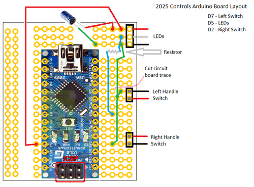
NOTE: the diagram is the top view, so take that into consideration when wiring
- Make Arduino Board (see board layout below)
- Label broken switches

Meeting Minutes
1/4 (KICKOFF!) (Sat)
Attendees: Sami, Byers, Eric
Work Completed:
- Concept drawings started
1/5 (Sun)
Attendees: Sami, Byers, Eric
Meeting Minutes:
- Continued concept drawings
- Looked at NON-Wi-Fi controllers
- Created Wiki page
- Broke Wiki page
- FIXED Wiki page! :)
- Looked and took measures of the new clips on drivers station (see concept ideas)
- Added concepts
1/7 (Tue)
Attendees: Sami
Meeting Minutes:
1/8 (Wed)
Attendees: Sami
Meeting Minutes:
1/9 (Thu)
Attendees: Sami, Arlo, Colin, Eric, Byers
Meeting Minutes:
1/11 (Sat)
Attendees: Sami, Colin, Arlo, Oliver, Eric, Byers, Sam
Meeting Minutes:
1/12 (Sun)
Attendees: Sami, Byers
Meeting Minutes:
1/14 (Tue)
Attendees: Sami, Colin, Arlo, Byers, Eric, Charlie
Meeting Minutes:
1/15 (Wed)
Attendees: Sami, Eric, Byers
Meeting Minutes:
1/16 (Thu)
Attendees: Sami, Colin, Arlo
Meeting Minutes:
- Figure out what's broken with the controller holder assembly
- Cap for the top of the handles
- End cap for the bottom of the handles
- Increase height for controllers: 4.25"
- Top (thicker material .093)
- ReCAD the laptop holder
- Get controller spacing fixed (2.5" between controller and keep out zone)
- Finalize length: 23.75"
- AC power and Ethernet bracket
- Add notch for keyboard cutout
1/18 (Sat)
Attendees: Sami, Colin, Oliver, Byers
Meeting Minutes:
- End cap for the bottom of the handles
- Fixed/ Added to the Handle Assembly
- Square cutouts for the handles
- PEM holes for laptop holder
- Notches for the AC power and Ethernet bracket
- PEM holes for controller holders
- Found magnetic latches
- Laptop Holder/Broken Switches (may just need to update drawings)
- Controller holder(s)
- Determine a method of keeping the top on the box - Will be doing the same method as Stronghold
- Find magnetic latches, get them on order. (Look in Design Info)
- Find magnetic latches, get them on order. (Look in Design Info)
1/19 (Sun)
Attendees: Sami, Byers, Colin, Eric
Meeting Minutes:
- Bottom box
- fish fonts with lots of fishy water fish
- Words in Laptop holder: DIVE
- 🏆MILESTONE - HANDLES COMLETED🏆
- machined handle bar and pole in shop
- drawings, except laptop tray, are done
- 3d printed parts - perfecto
- finished magnet integration with other components
1/21 (Tue)
Attendees: Sami, Colin, Arlo, Eric, Byers
Meeting Minutes:
1/23 (Thu)
Attendees: Sami, Colin, Byers
Meeting Minutes:
1/25 (Sat)
Attendees: Sami, Arlo, Byers, Colin
Meeting Minutes:
1/26 (Sun)
Attendees: Sami, Byers
Meeting Minutes:
- Holes for Camera Lens in top
- Knob (Holes for screws, clicky thing)
- Top Drawing (and Submit)
- Re - printed things from yesterday
1/28 (Tue)
Attendees: Sami, Colin, Oliver, Charlie, Byers, Eric
Meeting Minutes:
- Solder RJ45 Jack
- Trim Wires on knob
- Replace the terminal ends on broken switch things
- Test broken switches
1/29 (Wed)
Attendees: Sami, Eric, Gracie
Meeting Minutes:
- Fix and test broken switches
- Secure RJ45 Jack with appropriate secureness
- Found Nuts for Magnets
- Velcro controllers and their holders
1/30 (Thu)
Attendees: Sami, Byers
Meeting Minutes:
2/1 (Sat)
Attendees: Eric, Collin, Byers
Meeting Minutes:
- parts came in
- cut Lexan for lens
- test fit all the parts:
- cut PEM studs on top & bottom for magnets
- controller was hitting front magnet, drilled holes in controller holders to shift them a little towards the back
- filled sharp edges on bottom
- counter sunk holes for top parts and bottom for controller holders
- drilled holes in handle tubes for button wires
- added a ground wire to the extension cord, and cut shrink wrap for it
- determined all 4 magnets should be fine
- discussed layout for Arduino board
- painted parts (laptop tray, top & bottom)
2/2 (Sun)
Attendees: Byers, Eric, Oliver
Meeting Minutes:
- soldered wire to LEDs and double-sided taped them to the bottom
- soldered wires to the handle buttons, mounted buttons, and ran wires through the handles
- glued flash's clear part and the camera lens
- determined general location for hub, power supply, extension cord, and Arduino board
- mounted:
- power plug, extension cord, heated shrink wrap, attached ground wire
- laptop tray
- magnet 'bars' on the top
- controller holders
- foam grips
- handle caps and ends
- camera lens
- flash
- top handle
- clicky knob
- Velcro to laptop tray and the laptop
2/4 (Tue)
Attendees: Sami, Byers, Colin, Oliver, Arlo, Charlie
Meeting Minutes:
- Make Arduino Board
- Add connectors to handle switch wires
- put on magnets on bottom; adjusting so top of top is flush/slight below bottom's edges
- put in broken switches
- Velcro broken switch board (under switches, right side)
- Velcro USB hub (flat side to bottom of case, ports facing towards side of case; just under right side of laptop; connect to USB on right side of laptop, using a right-angle USB)
- connect controller cables to USB hub (use cable tie mount to help it stay connected to hub)
- Velcro extension (side attached to bottom of case, plug facing under the laptop; just under left side of laptop)
- Velcro laptop power supply (under laptop; connect to extension cord)
- Velcro Arduino board
- Connect LEDs and handle switches to Arduino board
- put in Power, connect right angle network cable to it (connects to laptop)
2/5 (Wed)
Attendees: Sami, Eric
Meeting Minutes:
- put in Ethernet, connect right angle network cable to it (connects to laptop)
- Cable from Arduino to right side of laptop (use cable tie mount near board to help it stay connected; use right angle USB at laptop)
- cord management
- USB Thumb drive extension cord
- Test Hub, control, controllers, and broken switches
2/6 (Thu)
Attendees: Collin, Byers
Meeting Minutes:
- labelled controllers
- touched up silver screws (need to re-check once dry)
- installed Arduino on the Controls laptop
2/8 (Sat)
Attendees: Sami, Colin, Eric, Byers
Meeting Minutes:
2/16 (Sat)
Attendees: Sami, Byers
Meeting Minutes:
2/27 (Thu)
Attendees: Sami, Byers
Meeting Minutes:
3/19 (Wed)
Attendees: Averill
Meeting Minutes:
Controls Rules 2025
- 6.3.2 OPERATOR CONSOLES
DRIVE TEAMS set up their OPERATOR CONSOLE as soon as the DRIVE TEAM from the previous MATCH has
cleared the area. OPERATOR CONSOLES must be compliant with all relevant rules, specifically those in section
8.9 OPERATOR CONSOLE. The OPERATOR CONSOLE is plugged into the team’s assigned DRIVER STATION, as
indicated on the team sign. Any control devices worn or held by their HUMAN PLAYERS and/or DRIVERS during
the MATCH must be disconnected from or set on or beside the OPERATOR CONSOLE before the MATCH can
begin. A DRIVE TEAM obstructing or delaying OPERATOR CONSOLE setup is at risk of violating G301.
For the purposes of FIRST Robotics Competition, any device connected to the
OPERATOR CONSOLE is considered a control device because REFEREES are not
expected to differentiate between devices that can or cannot control the ROBOT. - R904 *OPERATOR CONSOLE physical requirements. The OPERATOR CONSOLE must not
- be longer than 5 ft. (~152 cm), B. be deeper than 1 ft. 2 in. (~35 cm) (excluding any items that are held or worn by the DRIVERS
during the MATCH),
C. extend more than 6 ft. 6 in. (~198 cm) above the floor, or
D. attach to the FIELD (except via the loop tape as described in section 5.6.1 DRIVER STATIONS).
There is a 4 ft. 6 in. (~137 cm) long by 2 in. (nominal) wide strip of hook-and-loop
tape (“loop” side) along the center of the DRIVER STATION support shelf that
should be used to secure the OPERATOR CONSOLE to the shelf. See section
5.6.1 DRIVER STATIONS for details.
Please note that while there is no hard weight limit, OPERATOR CONSOLES that
weigh more than 30 lbs. (~13 kg.) will invite extra scrutiny as they are likely to
present unsafe circumstances.
- R907 *No AC inverters. OPERATOR CONSOLES must not contain AC inverters

2025 Controller Map (From 2/27/2025 @ 17:33)

Archives
- 2024:Controls
- 2023:Controls
- 2022:Controls
- 2020:Controls
- 2019:Controls
- 2018:Controls
- 2017:Controls
- 2016:Controls
- 2015:Electrical_Controls_Subteam
- 2014:Electrical_Controls_Subteam
- 2013:Electrical_Controls_Subteam
- 2012:Electrical_Controls
- 2011:Electrical_Controls
- 2010:Electrical_Controls
- 2009:Electrical_Controls