2013:Electrical Controls Subteam
From 1511Wookiee
Jump to navigationJump to search
Electrical Controls Design
To Do List When Metalwork Arrives
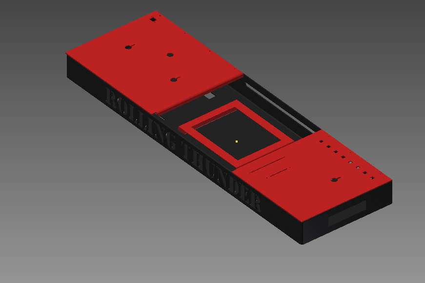
Control Board Layout
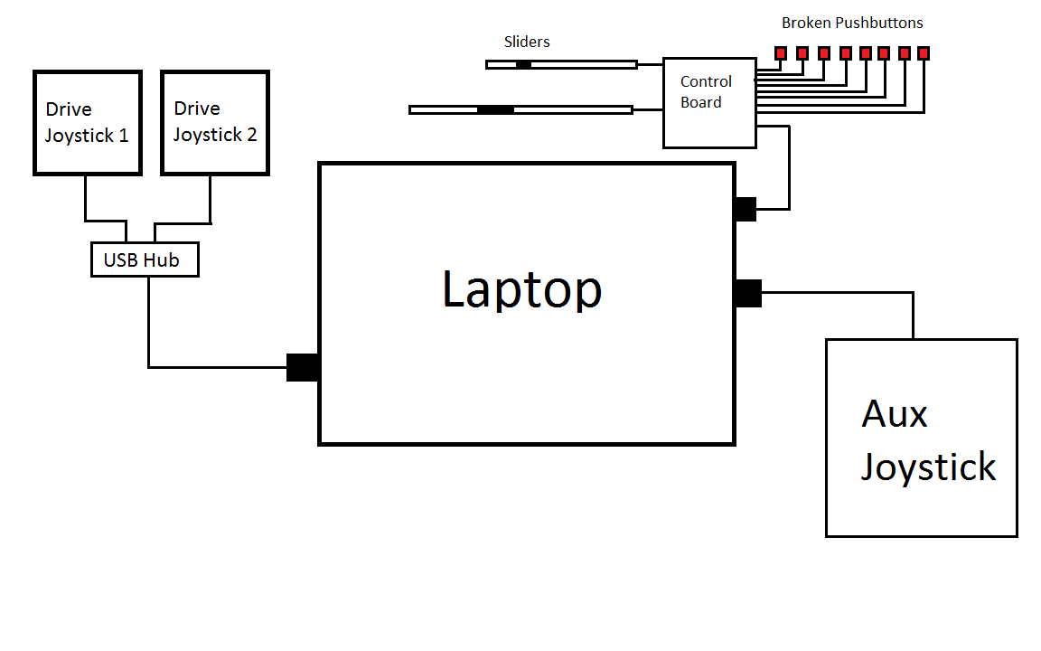
Block Diagram
Controls Overview
Resources
Operator Controls:
Joystick 1 (Drive Left)
| Button/Axis | Function |
| 1 | Turbo |
| 2 | Slow |
| 3 | Change to Shooter or Climber Mode (press and hold for Climber mode) |
| 4 | |
| 5 | |
| 6 | Debug Shooter |
| 7 | Debug Climber |
| 8 | |
| 9 | |
| 10 | Debug Target |
| 11 | Debug Drive |
| X-axis | |
| Y-axis | Drive Forward/Drive Backwards (Left Wheels) |
Joystick 2 (Drive Right)
| Button/Axis | Function |
| 1 | Turbo |
| 2 | Slow |
| 3 | Change to Shooter or Climber Mode (press and hold for Climber mode) |
| 4 | |
| 5 | |
| 6 | |
| 7 | |
| 8 | |
| 9 | |
| 10 | |
| 11 | |
| X-axis | |
| Y-axis | Drive Forward/Drive Backwards (Right Wheels) |
Joystick 3 (Aux)
| Button/Axis | Function |
| 1 | Shoot Disc |
| 2 | Feed Mode |
| 3 | Index Disc (Manually control index motor; only used when Storage Broken Switch is set) |
| 4 | Tilt Camera Down |
| 5 | Tilt Camera Up |
| 6 | Deploy |
| 7 | Climb (press and hold during entire climb; climb will stop when released; only used when Auto-Climb Broken Switch is NOT set) |
| 8 | Control Light Ring |
| 9 | |
| 10 | |
| 11 | |
| X-axis | |
| Y-axis | Manually climb for arm (up/down; only used when Auto-Climb Broken Switch is set) |
Joystick 4 (Extended IO)
| Button/Axis | Function |
| 1 | Storage Broken Switch (When broken, the aux driver will use a joystick button to move the fan blade motor (motor moves at constant speed and for the duration the button is pressed.) |
| 2 | Shooter Broken Switch (allow manual power input to shoot) |
| 3 | Lift (Angle Mech) Broken Switch. (When broken, the angle mech can still move either "up" or "down" if over dead center position. |
| 4 | Shooter/Storage Broken Switch (not allowed to shoot mode, control angle, or move storage motor!) |
| 5 | Auto-Climb Broken Switch (When broken, the primary driver will need to align arms with horizontal bars and aux driver will use buttons to move lifting arms. |
| 6 | Arm Pot Broken Switch (Auto-climb moves arms up/down at set constant speed, no PID) |
| 7 | Climbing Completely Broken Switch (Not allowed to climb mode; Set broken when any motors/servors/actuators are broken) |
| 8 | |
| 9 | |
| 10 | |
| 11 | |
| X-axis | Power potentiometer (Slider) |
| Y-axis | Angle Potentiometer (Slider) |
SmartDashboard
| Area | Description | Operation | Notes | Name | Data Type |
| Main | Camera Feed | This will be a direct feed from the camera. | The internet address will be based on the Team Number. | n/a | n/a |
| Main | Camera Crosshairs | The Crosshairs that show the center of the shooter, to help align shooter to fire discs appropriatly. | This would mostly be a simple line down the middle of the Camera Feed and across the middle of it to help line up where the disc will shoot. | n/a | n/a |
| Main | Power meter | Meter next to the Camera Feed that shows the robot shooter's current power. Would be a bar with a label next to it with a number representing power, scaling from 0 to 100 (???) | There is no real delay for desired power, so this is just shown as a one green bar. | Shooterpower | TBD |
| Main | Angle meter | Meter next to the Power Meter that displays what angle the robot is currently at and the desired angle (i.e. slider position). Would be a bar with a two labels next to it. | There are two colors for the bar, red and green. The green will go towards the red (the red will get smaller) as you reach your desired angle. The tip of where the red is is the desired angle, and the green is the current angle. There are also two numbers, one showing desired angle and one showing current angle. | Actualangle, Desiredangle | TBD |
| Setup Dialog | Discs in Robot | Set by driver prior to match to indicate how many discs they put in the robot for the match | Startdisks | TBD | |
| Setup Dialog | Team Number | Numberbox | Sets the team number for the robot to set the camera feed. Should remain constant until we change the IP address of the robot. Should not change very much. | n/a | n/a |
| Setup Dialog | Numeric Up/Down (aka spin box) | Autonomous Delay | Number of seconds before the auto mode starts. The number is from 0 to 9. | Delay | TBD |
| Setup Dialog | Auto-Mode | Select which autonomous mode to run. The number is from 0 to 3. | 0 means no autonomous is run | Automode | TBD |
Electrical Controls's Engineering Notebook
Week 1
- Came up with general idea for this year's design including;
- joystick placement
- laptop placement
- button placements
- switches and others
Week 2
- Created and sautered the basic frame
- Ended up changing the basic look of the controls into a much more fitting and organized design.
- Spray painted frame
Week 3
- Drilled and cut the holes into the frame, equally spaced inbetween each other.
Week 4
- Finished up the last of the holes and got started on installing the buttons and switches
Week 5
- Installed Joysticks for driver and auxillary driver
- Installed Laptop with Built-in Interface
Week 6
- Finished controls completely and ready for competitions.
Engineering Notebook Templates Available at:
Please Label All Notebook Pages 2013:Electrical Controls XX.XX to avoid confusion.


