2024:Controls
PROs and CONs List from previous years:
- PROs:
- Retractable handles
- Any other latches than roller latches
- Long hinges
- MEASURING correctly!:)
- CONs:
- Roller latches (they can't hold weight)
- Zippers (they break)
Overall Concept:
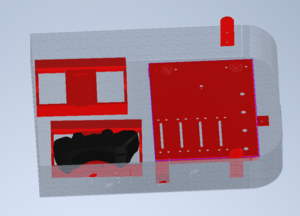
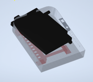
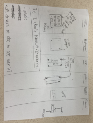
- Laptop Stand 2" high
- Amy said that L3Harris can weld the curve for us!
- 18" by 14"
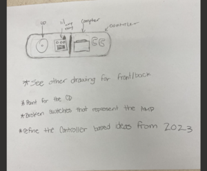
- 8 inches for Controllers to lay flat (PS5)
- make clips to hold in place
- Fixed handle
- Latch underneath?
- On other side of contolers:
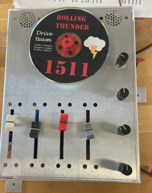
- CD on top with the sliders/butons/knobs below
- COLOR SCHEME:
- Black inside and out
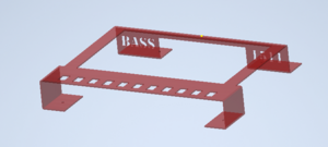
- Red for laptop holder and bling board
- Red for controller holders
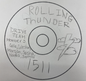
- CD is Black with Red lettering
|
|
|
Concept Drawings/Ideas:
- Paint splatter? again
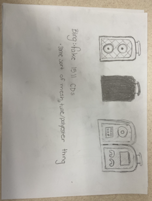
- Amp, speaker, or road case as the actual box
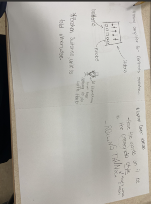
- 3D printed nobs
- handle
- reuse/improve controller cord holder (only if PS5)
- Team name in the CREScenDO outline?
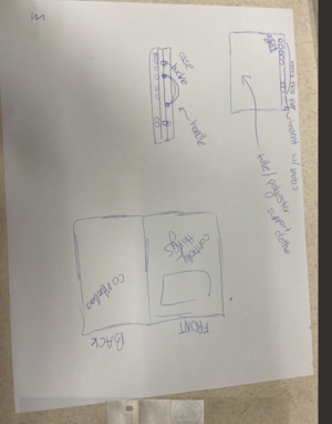
- Controls paper for laptop
- Chicken wire to resemble mesh
- Fake 1511 CDs
|
|
| ||
|
|
|
|
|
Design Info:
CADed parts:
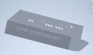
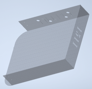
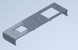
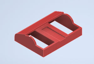
- Amp Box
- Speaker
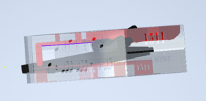
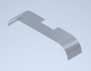
- Laptop Stand (Refined 2016 Design)
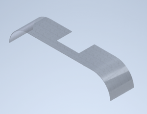
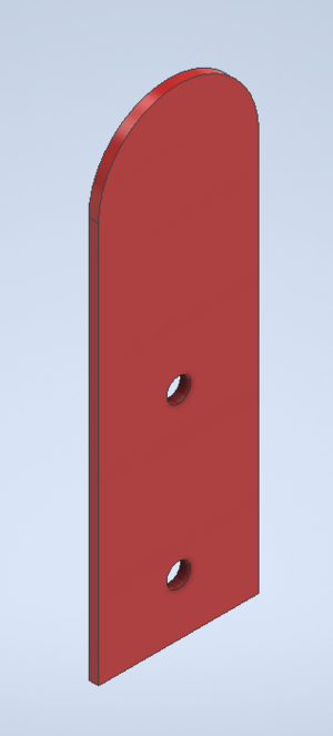
- Speaker Curve
3D printed parts:
- Controller Cord Holder (Refine 2023s)
- Latches for Controllers:
- Post for CD:
Bling:
- CD
- Mesh
- Sliders: Hole pem: BSO-632-12zi Hole size: 0.213 Center line to edge: 0.27
- :https://www.amazon.com/DAOKI-Logarithmic-Potentiometer-Arduino-Electronic/dp/B08SLPV4VD/ref=sr_1_19?dib=eyJ2IjoiMSJ9.TPGHYcRx8gEp9Qu1J2X4ad3zPT6v9ROndBU2d8Z86z7GjHj071QN20LucGBJIEps.rzujEJDQiAoS6N6jHZHtdidER6KmgsBBf9haxaxN7Fk&dib_tag=se&keywords=Slide+Potentiometer&qid=1705260984&sr=8-19
- Knobs
- Handle:https://www.amazon.com/dp/B07RXYDF7J/ref=sspa_dk_detail_0?pd_rd_i=B07RWZCTQP&pd_rd_w=bOttE&content-id=amzn1.sym.eb7c1ac5-7c51-4df5-ba34-ca810f1f119a&pf_rd_p=eb7c1ac5-7c51-4df5-ba34-ca810f1f119a&pf_rd_r=E72HN4Z8R5K007Q63W0J&pd_rd_wg=KMYE7&pd_rd_r=6f6c48e5-ec30-433d-a826-e7408fcee31f&s=musical-instruments&sp_csd=d2lkZ2V0TmFtZT1zcF9kZXRhaWw&th=1
- Broken Switch
- Hinge: https://www.amazon.com/Stainless-Continuous-Hinge-Bright-Annealed/dp/B07S85MT9G/ref=asc_df_B07S85MT9G/?tag=hyprod-20&linkCode=df0&hvadid=673687118827&hvpos=&hvnetw=g&hvrand=8210718651493454702&hvpone=&hvptwo=&hvqmt=&hvdev=c&hvdvcmdl=&hvlocint=&hvlocphy=1022882&hvtargid=pla-2203756691906&mcid=1d09b215000b371ea1ed399b883ea19d&th=1
- Latches: https://www.amazon.com/Penn-Elcom-L905-915Z-Butterfly-Latch/dp/B0006MZM8C/ref=sr_1_1?crid=3L3JKQUI3382C&dib=eyJ2IjoiMSJ9.ikSRrhyztVV-cwtSOgsL5N9MQrj0yXdkknYo9O295nbGjHj071QN20LucGBJIEps.UrzAt-NcigkVOzg1_JWikJXfYB5BwhpCTs_2GFVoQRo&dib_tag=se&keywords=L905%2F915Z&qid=1705276754&s=hi&sprefix=l905%2F915z%2Ctools%2C87&sr=1-1&th=1
- https://www.amazon.com/Reliable-Hardware-Company-RH-A3020BK-Butterfly/dp/B00JQYUEAC/ref=asc_df_B00JQYUEAC/?tag=hyprod-20&linkCode=df0&hvadid=193151859311&hvpos=&hvnetw=g&hvrand=7275364316301943114&hvpone=&hvptwo=&hvqmt=&hvdev=c&hvdvcmdl=&hvlocint=&hvlocphy=1022882&hvtargid=pla-311878510313&psc=1&mcid=c0c715df6e843da9a6691f7002e846ab&gclid=EAIaIQobChMI1aSI7svWgwMVIElHAR18AwwSEAQYCSABEgISdvD_BwEMusic Font: https://www.dafont.com/lasolsi-figuras.font
- Speaker and Mp3 Player
- Bling PCB
- Arduino Nano Every - https://www.amazon.com/Arduino-Nano-Every-headers-Mounted/dp/B07WWK29XF/ref=sr_1_6?crid=T4JY1BTPQI3D&keywords=nano+every&qid=1706469396&sprefix=nano+every%2Caps%2C90&sr=8-6
- pinout: https://content.arduino.cc/assets/Pinout-NANOevery_latest.pdf
- 8 Analog Inputs:
- sliders: 1) volume (A0); 2) LED brightness (A1); 3) LED pattern speed (A2); 4) TBD (A3)
- knobs: 1) on/off (A4); 2) EQ (A5); 3) song selection (A6); 4) pattern selection (A7)
- Digital Outputs:
- LED control signal (D5)
- Digital Inputs:
- CD encoder (D9 & D10) [Arduino can handle 5V on input pin]
- NOTE: leave room for USB cable to connect
- MP3 Player - https://wiki.dfrobot.com/DFPlayer_Mini_SKU_DFR0299
- VCC to Arduino 5V
- RX to 1K resistor to Arduino TX (yes RX goes to TX)
- TX to Arduino RX
- SPK_1 to both speaker red wires
- GND to Arduino GND
- SPK_2 to both speaker black wires
- NOTE: leave room to get SD card in and out
- Sliders (4.6K ohm):
- OTB pin goes to Arduino (A0 thru A3); GND pin to Arduino ground
- Knobs: (10K ohm):
- center pin to Arduino (A4 thru A7); GND pin to Arduino ground
- Speaker:
- red to MP3 pin SPK_1; black to MP3 pin SPK_2
- Encoder: see customer picture in reviews - https://www.amazon.com/uxcell-Encoder-Digital-Potentiometer-D-Shaft/dp/B07R6BZVBT/ref=sr_1_18?crid=SRJFGIJT5L8A&keywords=potentiometer+rotary+encoder&qid=1706402484&sprefix=potentiometer+rotary+encoder%2Caps%2C74&sr=8-18#customerReviews
- A to Arduino D9
- Common to Arduino GND
- B to Arduino D10
- VCC pin to Arduino 5V
- LEDs: needs capacitor and resister circuit we have always used
- Arduino 5V to LED strip 5V and Cap + (330uf or 470uf)
- Arduino GND to LED strip GND and Cap -
- Arduino D5 to resistor (120ohm ?) to LED Signal
- Arduino Nano Every - https://www.amazon.com/Arduino-Nano-Every-headers-Mounted/dp/B07WWK29XF/ref=sr_1_6?crid=T4JY1BTPQI3D&keywords=nano+every&qid=1706469396&sprefix=nano+every%2Caps%2C90&sr=8-6
To-Do:
Not Started:
In Process:
Completed:
- Added sections to the 2024: Controls page
- Read and added Driver Station specs and the rules for the controls
- Linked game manual to "Controls Rules 2024:" section
- Added all Build Season dates to page
- PROs and CONs list from previous years
- Brainstorm ideas for controls
- What kind of controllers do they want?- Ask (Main) Sasha, Coleston, Calla, Morgan (2nd) Sophia, Nadia
- Finish CADing the controls
- Cutouts on the sides (music notes as ROLLING THUNDER and 20th Anniversary)
- Support Beams/ Connecters so cutouts won’t break or fall out
- Other location for PEM Studs
- Find the appropriate handle
- Shop Drawings
- Update Assembly Log
- Put 2 copies in shop drawing binder
- Completed STEP files for the parts
- Color scheme
- Put CAD into Wookie
- Final Assembly
- Finish CD design
- Figured out how to do the sound
- CAD bling board
- Final Final Assembly
- Mapped out Ardino on paper
- Wire bling board
- Printed Post for the CD
- Measure speaker mesh
- see how speaker looks against black (white border or no) (NO White border)
- Takes Tools test(100%)
- post controller holder files in teams
- Where to mount handle?
- Mount and drill holes for latch
- Dry fit of controls
- Test post for the CD
- Find double sided tape for LED strips
- Test ethernet cable
- Find USB hub
- Find right angle ethernet connector
- Find LED strips
- Wired and tested LED Strips
- Clean up Controls Shelf in Shop Closet
- Paint controls
- Attach Velcro on other controller holder
- Take Game test(100%)
- Picture for speaker for outside
- Filmed and edit controls video
Meeting Minutes:
1/6 (KICKOFF!) (Sat)
Attendees: Sami, Lisa
Work Completed:
- Added sections to the 2024: Controls page
- Read and added Driver Station specs and the rules for the controls
- Linked game manual to "Controls Rules 2024:" section
- Started brainstorming different ideas for controls
- Started a PROs and CONs list from previous years
- Created a Concept Drawing/I Don't Knows/Concerns
- Added all Build Season dates to page
1/7 (Sun)
Attendees: Sami, Byers, Eric, Sophia
Work Completed:
- Created some more concept designs
- Took apart two old Control Cases
- Finished PROs and CONs list
1/9 (Tue)
Attendees: (N/A due to virtual meeting)
Work Completed: (N/A due to virtual meeting)
1/10 (Wed) Attendees: Sami, Byers Work Completed:
- Looked deeper into the controls design
- Asked Sasha what controllers; she then asked Calla; waiting now
1/11 (Thu)
Attendees: Sami, Monika, Geoff
Work Completed:
- Added to the Design Info section, about bling, CAD, and 3D prints
- Geoff attempted to help attempt CAD the controls
- PS5s are being used: confirmed by Sasha and Calla
- Added some links to items that will be needed and others
- CADed a curve and a almost box
1/13 (Sat) (INTERGRATION @ 11:30am!)
Attendees: Sami, Erin, Byers, Monika, Robert
Work Completed:
- Sami CADed like a pro:)
- Prepared for Intergration
- They would like the controls to be smaller than 2023
- Discused the final design
- Started assembly/CAD
1/14 (Sun)
Attendees: Sami, Byers, Eric
Work Completed:
- Created notches for the hinge
- Notch for Hinge and Latch
- Holes for Laptop and Bling
- CADed alot (almost done)
1/16 (Tue) (INTERGRATION @ 6:30pm!)
Attendees: Sami, Sophia, Erin, Eric
Work Completed:
- Finished CADing the cutouts
- Created Closer Alignment piece
- Color scheme
- Put CAD into Wookie
- Final Assembly
1/17 (Wed)
Attendees:
Work Completed:
1/18 (Thu)
Attendees: Sami, Byers
Work Completed:
- CADed
- Shop Drawings
1/20 (Sat) (INTERGRATION @ 11:30am!)
Attendees: Sami, Byers, Eric
Work Completed:
- Power and Ethernet CADed
- More shop drawings finished
1/21 (Sun)
Attendees: Sami, Byers, Eric, Sophia Work Completed:
- Find the appropriate handle
- Shop Drawings
- Update Assembly Log
- Put 2 copies in shop drawing binder
- Created CD design ideas
1/23 (Tue) (INTERGRATION @ 6:30pm!)
Attendees: Sami, Eric
Work Completed:
- Created STEP files for Top, Bottom, and Laptop Holder
- Started cutouts for bling board
- Tested
1/24 (Wed)
Attendees:
Work Completed:
1/25 (Thu)
Attendees: Sami, Byers
Work Completed:
- Worked on the bling board
- Sent controller holder tests to Mr. Weisbord
1/27 (Sat)
Attendees: Sami, Byers, Eric
Work Completed:
- Tested sliders
- Finalized where things went on bling board
- Obtained SD card, latch, and speakers
- Finalized CD design
1/28 (Sun)
Attendees: Sami, Byers
Work Completed:
- Made Shop drawings for the 3D parts
- Cleaned up the 3D parts for TESTING
- Shop drawing for bling board
- All other tasks completed to for it
- Made a new controller holder design
- sent it in with all its requirments
1/30 (Tue)
Attendees: Sami, Eric
Work Completed:
- Final Final Assembly
- Mapped out Ardino on paper
- gathered supplies and put it in RED bin for the Ardino board
- Made copies of the paper so we each have a copy and don"t lose things
1/31 (Wed)
Attendees:
Work Completed:
2/1 (Thu)
Attendees: Sami, Chris
Work Completed:
- I stole Chris cause he can do Adobe Illistaror
- worked on speaker
- I tested holder, it fit i think
2/3 (Sat)
Attendees: Sami, Byers, Eric
Work Completed:
- Modified Controller holder and sent in
- Made a the CD post and sent in
- Wire bling board
2/4 (Sun)
Attendees: Sami, Byers
Work Completed:
- Worked on code for bling
- conected wires to sliders and knobs
- Found hardware
- debugged and fixed bling board
- started painting the laptop holder
- ferifed controller holder
- started another controller holder
- printed CD onto a label
- Took Tools Test
2/6 (Tue)
Attendees: Sami Work Completed:
- Took Tools test
- Obtained post for CD, still need to test
- Measured speaker mesh, almost every part could fit, so a lot to work with for options
- Found out that 3D printer DIED, like dead, dead
- NO White border for speaker
2/7 (Wed)
Attendees: Sami
Work Completed:
- Takes Tools test(100%)
- post controller holder files in teams
- Downloaded STEP file for cable holder
2/8 (Thu)
Attendees: Sami
Work Completed:
- Organized To-Do list
2/10 (Sat)
Attendees: Sami, Byers
Work Completed:
- Test fitted new parts (all)
- Sent back bling board (standoffs where not pressed in)
- Finished CD
- Velcroed laptop and holder
- Started painting
- Made holes for latch/handle
- Made holes for controller holder
- Find double sided tape for LED strips
2/11 (Sun)
Attendees: Sami, Byers, Eric
Work Completed:
- Painted controls
- Tested ethernet cable
- Cleaned out closet
- Ordered USB hub
- Ordered right angle ethernet
- Found LED Strips
- Wired and tested LED Strips
2/13 (Tue)
Attendees: Sami, Byers, Eric
Work Completed:
- Paint control
- Attach Velcro on other controller holder
- Took Game Test (11/42;16/42)
- Did other Final Assembly Things
2/14 (Wed)
Attendees: Sami
Work Completed:
- Took Game Test (25/42;24/42)
2/15 (Thu)
Attendees: Sami
Work Completed:
- Took Game Test (31/42;37/42)
2/16 (Fri) Attendees: Sami Work Completed:
- Took Game Test (40/42;42/42)
- Put three sliders on bord
2/17 (Sat)
Attendees: Sami, Gracie, Byers, Eric
Work Completed:
- COMPLETED THE CONTROLS!:)
2/18 (Sun)
Attendees: Sami, Byers
Work Completed:
- Refined the code
2/20 (Tue)
Attendees: Sami, Shopia, Brennan
Work Completed:
Filmed and edit controls video
2/21 (Wed)
Attendees:
Work Completed:
2/22 (Thu)
Attendees:
Work Completed:
2/24 (Sat)
Attendees:
Work Completed:
2/25 (RALLY!) (Sun)
Attendees:
Work Completed:
2/27 (Tue)
Attendees:
Work Completed:
2/28 (Wed)
Attendees:
Work Completed:
2/29 (Thu)
Attendees:
Work Completed:
3/2 (Sat)
Attendees: Byers
Work Completed:
Labelled broken switches. Tweaked the controller cable clip. 3/3 (Sun)
Attendees:
Work Completed:
3/5 (Tue)
Attendees:
Work Completed:
3/6 (Wed)
Attendees:
Work Completed:
3/7 (Thu)
Attendees:
Work Completed:
3/9 (Sat)
Attendees: Byers
Work Completed:
Controller holder clip needed more changes. 3/10 (Sun)
Attendees:
Work Completed:
3/12 (Tue)
Attendees:
Work Completed:
3/13 (Wed)
Attendees:
Work Completed:
Controls Rules 2024: https://firstfrc.blob.core.windows.net/frc2024/Manual/2024GameManual.pdf
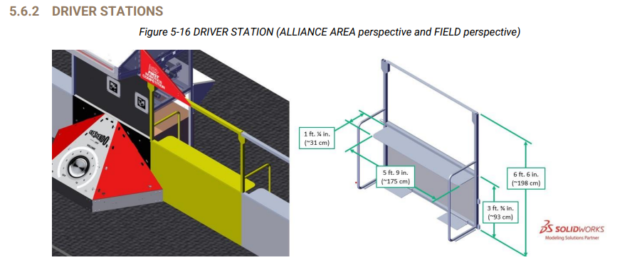
A DRIVER STATION is 1 of 3 assemblies within an ALLIANCE WALL behind which a DRIVE TEAM operates their
ROBOT. Each DRIVER STATION is made from a 3 ft. ¾ in. (~93 cm) tall diamond plate base topped with a 3 ft. 6 in. (~107 cm) tall transparent plastic sheet and a top rail. An aluminum shelf is attached to each DRIVER
STATION to support an OPERATOR CONSOLE. The shelf is 5 ft. 9 in. (~175 cm) wide and 1 ft. ¼ in. (~31 cm)
deep. There is a 4 ft. 6 in. (~137 cm) long by 2 in. (nominal) wide strip of hook-and-loop tape (“loop” side)
along the center of the support shelf that may be used to secure the OPERATOR CONSOLE to the shelf.
'
R901 *Use the specified Driver Station Software. The Driver Station Software provided by National
Instruments (install instructions found here) is the only application permitted to specify and
communicate the operating mode (i.e. AUTO/TELEOP) and operating state (Enable/Disable) to the
ROBOT. The Driver Station Software must be version 24.1 or newer.
[Teams are permitted to use a portable computing device of their choice (laptop
computer, tablet, etc.) to host the Driver Station Software while participating in
MATCHES.]
R902 *The OPERATOR CONSOLE must have a visible display. The OPERATOR CONSOLE, the set of
COMPONENTS and MECHANISMS used by the DRIVERS and/or HUMAN PLAYERS to relay commands
to the ROBOT, must include a graphic display to present the Driver Station Software diagnostic
information. It must be positioned within the OPERATOR CONSOLE so that the screen display can be
clearly seen during inspection and in a MATCH.
R903 *Connect FMS Ethernet directly to the OPERATOR CONSOLE. Devices hosting the Driver Station
Software must only interface with the FMS via the Ethernet cable provided at the DRIVER STATION (e.g.
not through a switch). Teams may connect the FMS Ethernet cable to the device running the Driver
Station Software directly via an Ethernet pigtail, or with a single-port Ethernet converter (e.g. docking
station, USB-Ethernet converter, Thunderbolt-Ethernet converter, etc.). The Ethernet port on the
OPERATOR CONSOLE must be easily and quickly accessible.
[Teams are strongly encouraged to use pigtails on the Ethernet port used to
connect to the FMS. Such pigtails will reduce wear and tear on the device’s port
and, with proper strain relief employed, will protect the port from accidental
damage.]
R904 *OPERATOR CONSOLE physical requirements. The OPERATOR CONSOLE must not
A. be longer than 5 ft. (~152 cm),
B. be deeper than 1 ft. 2 in. (~35 cm) (excluding any items that are held or worn by the DRIVERS
during the MATCH),
C. extend more than 6 ft. 6 in. (~198 cm) above the floor, or
D. attach to the FIELD (except via the loop tape as described in Section 5.6.2 DRIVER STATIONS).
[There is a 4 ft. 6 in. (~137 cm) long by 2 in. (nominal) wide strip of hook-and-loop
tape (“loop” side) along the center of the DRIVER STATION support shelf that
should be used to secure the OPERATOR CONSOLE to the shelf. See Section
5.6.2 DRIVER STATIONS for details.
Please note that while there is no hard weight limit, OPERATOR CONSOLES that
weigh more than 30 lbs. (~13 kg.) will invite extra scrutiny as they are likely to
present unsafe circumstances.]
R905 *FIELD wireless only. Other than the system provided by the FIELD, no other form of wireless
communications shall be used to communicate to, from, or within the OPERATOR CONSOLE.
[Examples of prohibited wireless systems include, but are not limited to, active
wireless network cards and Bluetooth devices. For the case of the FIRST
Robotics Competition, a motion sensing input device (e.g. Microsoft Kinect) is
not considered wireless communication and is allowed.]
R906 *No unsafe OPERATOR CONSOLES. OPERATOR CONSOLES shall not be made using hazardous
materials, be unsafe, cause an unsafe condition, or interfere with other DRIVE TEAMS or the operation
of other ROBOTS.
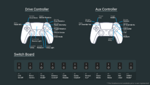
2024 Controller Map
