2022:Controls
About how much everything weights
- The Laptop: 6.12 lbs.
- The Metal Base with Controls: 5.09 lbs. x2
- The Controller (as PS5 or Xbox): 0.5 lbs. x2
- The Suitcase: 7.3 lbs.
- Everything will sum up to about 17.3 lbs. (if you add plus one more metal base and one more controller)
To Order
- https://www.amazon.com/Famido-Wireless-Controller-Vibration-Compatible/dp/B09GLLJKHM/ref=sr_1_13?crid=2GJ9DRN1YZXJS&keywords=ps5%2Bcontroller&qid=1642285311&s=electronics&sprefix=ps5%2Bcontroller%2Celectronics%2C64&sr=1-13&th=1 (we need 2)
- https://www.amazon.com/Charging-Controller-Replacement-Accessories-Nintendo/dp/B08M8W189S?ref_=ast_slp_dp&th=1&tag=drivereasycom-20 (we need 2 probably)
- https://www.amazon.com/AmazonBasics-Hardside-Spinner-Luggage-20-Inch/dp/B071VG5N9D/ref=sr_1_4?crid=1DWX1Z69LEUXS&keywords=amazonbasics%2Bhard%2Bshell&qid=1642364918&s=apparel&sprefix=amazon%2Bbasics%2Bhard%2Bshell%2Cfashion-luggage%2C50&sr=1-4&th=1 (we need 1)
- https://www.digikey.com/en/products/detail/e-switch/KC18A9-501NPS/1804553 (we need 2)
- https://www.digikey.com/en/products/detail/switch-components/TD1-1A-DC-3-B/11492895 (we need 5)
- https://www.amazon.com/Baomain-Button-Switch-Latching-Rectangular/dp/B01N1RGTPH/ref=sr_1_53?crid=HEZR5HXMDCW0&keywords=latching+push-button&qid=1642551750&s=industrial&sprefix=latching+push-button%2Cindustrial%2C74&sr=1-53#Ask (we need 10)
- https://www.amazon.com/Encoder-Controllers-Arcade-Joystick-Cables/dp/B01LZBFMWG/ref=sr_1_10?keywords=zero+delay+usb+encoder&qid=1642885332&sprefix=zero+del%2Caps%2C76&sr=8-10 (2 needed)
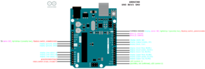
Arduino Pinout
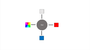
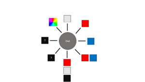
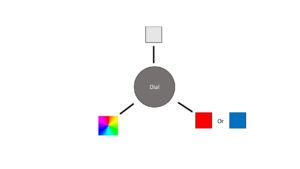
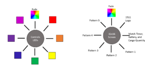
LED lights ideas
- The question marks mean that the driver or the team would decide what they would want.\
- Note for combo 3, black isnt possible without turning an led off
Broken switches controls layout (CAD)
File:Controls v7 (Better Layout).iptFile:Controls v6.5 layout alternate.ipt
Misc. parts links
- https://hitecrcd.com/products/servos/analog/sport-2/hs-322hd/product
- https://www.amazon.com/SJ-JX-2-Player-Joystick-Raspberry/dp/B07QQP8L85?ref_=ast_sto_dp&th=1 (USB encoder)
- https://www.amazon.com/Toggle-Upgrade-Adjustable-Release-Latches/dp/B08R8P37VB/ref=pd_sbs_1/136-8242267-2364221?pd_rd_w=FK1eV&pf_rd_p=0a3ad226-8a77-4898-9a99-63ffeb1aef90&pf_rd_r=RSJEEWY3V4SZTCZVXVGZ&pd_rd_r=8540734d-4f59-4b5e-8088-bf4df8498a45&pd_rd_wg=C0YcY&pd_rd_i=B08R8P37VB&psc=1 (latches to keep suitcase closed)
- https://catalog.pemnet.com/viewitems/thru-hole-threaded-standoffs-types-so-soa-sos/u-hole-threaded-standoffs-types-so-soa-sos-unified
Possible switches we would need
- https://www.digikey.com/en/products/detail/switch-components/TD1-1A-DC-3-R/11492919
- https://www.digikey.com/en/products/detail/switch-components/TD1-1A-DC-3-B/11492895
- https://www.digikey.com/en/products/detail/e-switch/KC18A9-501NPS/1804553
Measurements for switches
- https://www.nteinc.com/switches/pdf/toggle-illum.pdf#page=1
- https://www.nteinc.com/switches/pdf/toggle-illum.pdf#page=2
- https://www.onpowbutton.com/download/2015020911103373499.pdf#page=3
- https://www.nkkswitches.com/pdf/stoggleslowcap.pdf#page=4
Overall Concept
Ideas
- https://ccntservice.airbus.com/apps/cockpits/a380/
- https://www.google.com/search?q=instrument+panel+screen+cockpits&safe=active&rlz=1C1GCEA_enUS988US988&source=lnms&tbm=isch&sa=X&ved=2ahUKEwjJypDp1bT1AhUQlIkEHZhLAqcQ_AUoAnoECAIQBA&biw=2048&bih=1010&dpr=1.25&surl=1#imgrc=1d8bVQjBNyXwbM
- https://www.google.com/search?q=instrument+panel+screen+cockpits&safe=active&rlz=1C1GCEA_enUS988US988&source=lnms&tbm=isch&sa=X&ved=2ahUKEwjJypDp1bT1AhUQlIkEHZhLAqcQ_AUoAnoECAIQBA&biw=2048&bih=1010&dpr=1.25&surl=1#imgrc=RzuDufz4GFshIM
- https://www.google.com/search?q=instrument+panel+screen+cockpits&safe=active&rlz=1C1GCEA_enUS988US988&source=lnms&tbm=isch&sa=X&ved=2ahUKEwjJypDp1bT1AhUQlIkEHZhLAqcQ_AUoAnoECAIQBA&biw=2048&bih=1010&dpr=1.25&surl=1#imgrc=RzuDufz4GFshIM&imgdii=LS5luSMymSLzhM
- https://www.google.com/search?q=instrument+panel+screen+cockpits&safe=active&rlz=1C1GCEA_enUS988US988&source=lnms&tbm=isch&sa=X&ved=2ahUKEwjJypDp1bT1AhUQlIkEHZhLAqcQ_AUoAnoECAIQBA&biw=2048&bih=1010&dpr=1.25&surl=1#imgrc=RzuDufz4GFshIM&imgdii=LS5luSMymSLzhM
- suitcases:
- https://www.amazon.com/gp/slredirect/picassoRedirect.html/ref=sspa_dk_rhf_search_pt_sub_6?ie=UTF8&adId=A097990730AYJC65UKVRS&adOffset=0&qualifier=1642360206&id=2227095588892004&widgetName=sp_rhf_search&url=%2FReplacement-Luggage-Suitcase-Plastic-Replace%2Fdp%2FB07K5BHSLG%3Fpsc%3D1%26pd_rd_w%3DiqcNo%26pf_rd_p%3D25248977-401c-428a-bf0f-e1aa228a5886%26pf_rd_r%3D45TPGP0EMQ2Y1ANTBEE1%26pd_rd_r%3Db3206c38-bb7d-498d-8aa6-f55c6443e141%26pd_rd_wg%3Dyxe0k%26ref_%3Dsspa_dk_rhf_search_pt_sub_6
- https://www.amazon.com/Rockland-20-Polycarbonate-Carry-Camo/dp/B00DQRQYZY/ref=sr_1_17?crid=2ZRSPL4CG0MQY&keywords=amazon+suitcase+14+in+deep+hard+shell&qid=1642360628&s=apparel&sprefix=amazon+suitcase+14+in+deep+hard+cheel%2Cfashion-luggage%2C55&sr=1-17
- https://www.amazon.com/COOLIFE-Luggage-Suitcase-Hardshell-Lightweight/dp/B01M0AN6E7/ref=sr_1_54?crid=2ZRSPL4CG0MQY&keywords=amazon+suitcase+14+in+deep+hard+shell&qid=1642360848&s=apparel&sprefix=amazon+suitcase+14+in+deep+hard+cheel%2Cfashion-luggage%2C55&sr=1-54
- actual suitcase that we will use:
- https://www.amazon.com/AmazonBasics-Hardside-Spinner-Luggage-20-Inch/dp/B071VG5N9D/ref=sr_1_4?crid=1DWX1Z69LEUXS&keywords=amazonbasics%2Bhard%2Bshell&qid=1642364918&s=apparel&sprefix=amazon%2Bbasics%2Bhard%2Bshell%2Cfashion-luggage%2C50&sr=1-4&th=1
To Do
Not Started
- Update assembly-level model to add in laptop and aux brackets and any other models that we have: Noah was working on switches, laptop, laptop power brick, etc. Create models for these or use models from prior years if available.
- Choose LED patterns
- Servo patterns?
- Come up with color scheme for the case as well as the aux and laptop panels
In Process
- Wiring diagram for broken switches
- Figure out how the suitcase will be closed if we remove the existing hinge. Will we be able to modify the zipper, will we need to add latches, etc. Need to brainstorm/think about this. We may need to add a cable/chain to keep the two halves together so strain is not placed on the wires that will need to run between the two halves.
- We have an idea, split the suitcase where the "expanding" section is. If we can find a zipper insertion pin and zipper end we can add these so that the zipper can be zippered back up.
- (Colin) Create models for flight instruments, these models should be submitted for 3D printing when they are complete.
- (Noah) Understand how Arduino will work
- How to talk to the display
- Come up with pinout
Completed
- Create models for dials (may be updating existing model). Note that the two dials have different shaft sizes so we may need two different models even if the basic design is the same. These should have official part numbers.
- Finish the models of the computer/aux controls
- Update CAD for new servos (Hitec)
- Add holes in both laptop and aux brackets (4 in a rectangle roughly 5" x 3") for standoffs to hold boards for electronics. Same size standoffs as the servos.
- Arduino is ~ 3.2" x 2.2"; there is a simple CAD of the size, not including any perf board; looks like it would fit between the pots (shortest path to pots)
- UDB board is ~1.5" x 3.5"; have an old perf board that is 3.5" x 6.75"; there is a simple CAD of that size; looks like it would fit between servos (shortest path for button wires).
- Figure out mounting for display. May just have to make the rectangular cutout a little smaller and mount the display on the top. See if we can find detailed dimensions of the holes or download 3D model if possible.
- Create shop drawings for the two pieces.
- Put the LED dot-matrix on the shopping list
- How to control the servos - the current one did work with Arduino, will need to use Hitec
- How to control the programmable LEDs
- Add holes for the servo standoffs
- Need to order longer USB cables for PS4/PS5 controller (Amazon.com: 2 Pack 10FT PS5 USB C Cord)
- Need to order PS4/PS5 controller (PS4 controller)
- At diner prepare to present the model and explain everything to the people. Answer peoples questions if they have any. take in notes on comments or what they think we should add.
- Using PS4/PS5 (or Xbox if PS not possible) for primary driver [was confirmed with Isaac on 1/15/22]
- PS4/PS5 control works with Windows 10 (PS4 to PC; PS5 to PC)
- If you haven't before check out the controls in the closet.
- Brainstorm themes/concepts, be ready Saturday to share.
- Research joysticks.
- If we are going to do a swerve drive we need to understand how it will be controlled.
- Keep finding switches we are going to use look over what we have in the shop put them in a separate box so we know we have to use them, such as collecting data sheets and measurements. Put them in the wiki.
- After we present(didn't present yet), we should give the suitcase back to Niccole, and put the pieces inside back in place.
- Updated sheet metal to 0.092" thickness on both models.
Controls Assignments
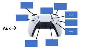
Aux
Drive
Bling
Useful Links
- Subteam Student/Mentor Photos
- Zero Delay USB Joystick Encoder
- Joystick Controller Board
- Analog Slide Position
- Among Us
- Example push buttons (need to make sure we pick ones that stay pushed; are not momentary):
- Two USB hub options:
PSoC Creator IDE
- Download latest "PSoC Creator" from Cypress (http://www.cypress.com/products/psoc-creator-integrated-design-environment-ide) and install it (use Typical install; at end run Updater and maek sure you have the latest stuff)
- For user name and password, you can use: mailme@mailinator.com mailme123
Toolkits and Board Driver Install
- Get controls2019 from SVN
- Run: vcredist_x86.exe
- Run: USBSerialSDKSetup.exe (do Typical install; at end run Updater and maek sure you have the latest stuff)
- Run: CY8CKIT04942xxSetupOnlyPackage_revSA.exe (do Typical install; at end run Updater and make sure you have the latest stuff)
- While you press and hold the SW1 Prog button on the cypress board, plug in the USB cable to the PC (it will take a while for it to install 5 drivers).
Build/Program
- Open PSoC Creator (Start -> Programs -> Cypress -> PSoC Creator -> PSoC Creator)
- Open project: File -> Open -> Project/Workspace; then browse to Desktop/FRC2020/trunk/controls/SCB_Bootloader/SCB_Bootloader.cywrk)
- Build project: Build -> Build All Projects
- While you press and hold the SW1 Prog button on the cypress board, plug in the USB cable to the PC
- Download Boot Loader:
- open programmer: Tools -> Bootloader Host
- set 'File' to C:\Users\Robotics\Desktop\FRC2020\trunk\controls\SCB_Bootloader\Bootloadable Blinking LED.cydsn\CortexM0\ARM_GCC_541\Debug\Bootloadable Blinking LED.cyacd
- select the com port for the cypress board
- set Baud to 115200; Data Bits 8; Stop Bits 1; Parity None
- download program: Actions -> Program
Meeting Minutes
1/15
Attendees: Colin, Sam, Olga, Mr. Byers
Work Completed:
- confirmed primary controller
- looked at controls from prior years
- sketching concepts
1/16
Attendees: Colin, Sam, Olga, Noah, Eric.
Work Completed:
- Found suitcase
- Found way to make suitcase work
- confirmed that we are using two controllers ( probably ps5 )
- Worked out design
- Got measurements
- Started CAD work
- measured buttons
1/18
Attendees: Colin, Sam, Eric, Noah, Tanner
Work Completed:
- Basic design for control plate made in CAD.
1/19
Attendees: Tanner, Sam, Colin
Work Completed
- We found out that we don't actually need to control the shooter speed (we no longer need an analog dial)
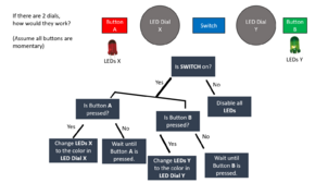
- Since we now have an extra dial space, we are considering using 2 dials to control the lights (ex. one for patterns, one for solid colors)
- We found out that we should have 5 broker switches and 15 broker buttons
- Basic design for computer holder panel made.
1/20
Attendees: Sam, Olga
Work Completed:
- Created a "flowchart" of how the LED dials could work
- Changed the number of broke buttons on the CAD model from 10 to 15
1/22
Attendees: Colin, Noah, Sam, Olga, Eric, Byers
Work Completed:
- Found and modified the Detailed CAD model of the controls (added holes for buttons, servos, and switches)
- Found a datasheet and link for the rotary switch
- made a to-buy list
- Measured Servos (math)
1/23
Attendees: Sam, Colin, Olga, Noah
Work Completed:
- Made CAD models for buttons/switches and tested (in an assembly file) to see if they fit in the detailed CAD model of the control panel
- Tested some software stuff for the LED dot-matrix
1/25
Attendees: Colin, Sam, Olga
Work Completed:
- Continued to make CAD models for buttons/switches and tested (in an assembly file) to see if they fit in the detailed CAD model of the control panel
1/26
Attendees: Sam, Colin
- Work Completed: Finished detailed CAD models of the square buttons and red switch (they fit in the aux controls)
- Made a weighted-analysis chart for options for airflow shape
- Made a CAD model of a background for a servos
1/27
Attendees: Sam, Noah, Colin
Work Completed:
- Tested LEDs
- Assembled the dial frames in the aux controls assembly
- Unboxed some parts that came in the mail
1/29
Attendees: Sam, Noah, Byers
Work Completed:
- Programming
- straightened out controls drawer.
- tested PS4 controller with Dashboard - it works! No special drivers needed at all.
- Determined relative sizes for USB and Arduino boards.
- Created a LED test board for Noah (Noah will borrow bread board, servos, LED test board)
1/30
Attendees: Colin, Eric, Noah, Sam
Work Completed:
- LEDs Programming
- Made/finished a Shop Drawing of the laptop bracket
- Edited the Sheetmetal cads to be more accurate
- Completed finished Shop drawing of AUX Controls
- Put in all holes for boards.
2/1
Attendees: Noah, Sam
Work Completed:
- Planed out ideas for suitcase
- received equimpment
- Arduino pinout talked about
2/2
Attendees: Colin
Work Completed:
2/3
Attendees:
Work Completed:
2/5
Attendees: Noah, Byers
Work Completed:
- pinout of Arduino
- Started to think about display ideas
- created a test broken switches board (so programmers have something while being able to work on controls)
- created perf board, that goes between servos, for the Arduino; also mounted Arduino
2/6
Attendees:
Work Completed:
2/8
Attendees:
Work Completed:
2/9
Attendees:
Work Completed:
2/10
Attendees:
Work Completed:
2/12
Attendees:
Work Completed:
2/13
Attendees:
Work Completed:
2/15
Attendees:
Work Completed:
2/16
Attendees:
Work Completed:
2/17
Attendees:
Work Completed:
2/19
Attendees:
Work Completed:
2/20
Attendees:
Work Completed:
Controls Rules
9.9 OPERATOR CONSOLE R901 *Use the specified Driver Station Software. The Driver Station Software provided by National Instruments (install instructions found here) is the only application permitted to specify and communicate the operating mode (i.e. AUTO/TELEOP) and operating state (Enable/Disable) to the ROBOT. The Driver Station Software must be version 22.0 or newer.
Teams are permitted to use a portable computing device of their choice (laptop computer, tablet, etc.) to host the Driver Station Software while participating in MATCHES.
R902 *The OPERATOR CONSOLE must have a visible display. The OPERATOR CONSOLE, the set of COMPONENTS and MECHANISMS used by the DRIVERS and/or HUMAN PLAYERS to relay commands to the ROBOT, must include a graphic display to present the Driver Station Software diagnostic information. It must be positioned within the OPERATOR CONSOLE so that the screen display can be clearly seen during inspection and in a MATCH.
R903 *Connect FMS Ethernet directly to the OPERATOR CONSOLE. Devices hosting the Driver Station Software must only interface with the FMS via the Ethernet cable provided at the DRIVER STATION (e.g. not through a switch). Teams may connect the FMS Ethernet cable to the device running the Driver Station Software directly via an Ethernet pigtail, or with a single-port Ethernet converter (e.g. docking station, USB-Ethernet converter, Thunderbolt-Ethernet converter, etc.). The Ethernet port on the OPERATOR CONSOLE must be easily and quickly accessible.
Teams are strongly encouraged to use pigtails on the Ethernet port used to connect to the FMS. Such pigtails will reduce wear and tear on the device’s port and, with proper strain relief employed, will protect the port from accidental damage.
R904 *OPERATOR CONSOLE physical requirements. The OPERATOR CONSOLE must not A. be longer than 5 ft. (~152 cm), B. be deeper than 1 ft. 2 in. (~35 cm) (excluding any items that are held or worn by the DRIVERS during the MATCH), C. extend more than 6 ft. 6 in. (~198 cm) above the floor, or D. attach to the FIELD (except as permitted by G301).
There is a 4 ft. 6 in. (~137 cm) long by 2 in. (nominal) wide strip of hook-and-loop tape (“loop” side) along the center of the DRIVER STATION support shelf that should be used to secure the OPERATOR CONSOLE to the shelf, per G301. See DRIVER STATION for details.
Please note that while there is no hard weight limit, OPERATOR CONSOLES that weigh more than 30 lbs. (~13 kg.) will invite extra scrutiny as they are likely to present unsafe circumstances.
R905 *FIELD wireless only. Other than the system provided by the FIELD, no other form of wireless communications shall be used to communicate to, from, or within the OPERATOR CONSOLE.
Examples of prohibited wireless systems include, but are not limited to, active wireless network cards and Bluetooth devices. For the case of the FIRST Robotics Competition, a motion sensing input device (e.g. Microsoft Kinect) is not considered wireless communication and is allowed.
R906 *No unsafe OPERATOR CONSOLES. OPERATOR CONSOLES shall not be made using hazardous materials, be unsafe, cause an unsafe condition, or interfere with other DRIVE TEAMS or the operation of other ROBOTS.
