2023:Controls
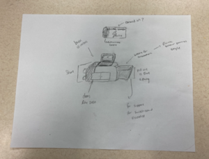
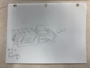
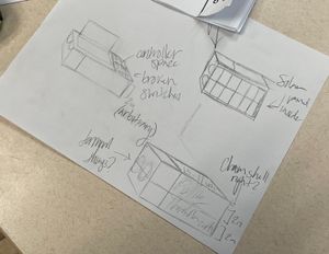
Overall Concept
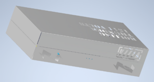
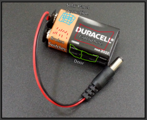
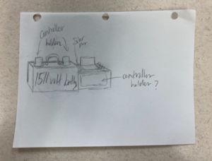
- 9V battery shape ("1511 Volts")
- Two (2) PS5 controllers
- Piano-hinged top that opens to the right
- Latches on the left side
- The bottom section will contain:
- One (1) Laptop
- Two (2) controllers (to right of the laptop, towards the back)
- Twelve (12) broken switches (to right of laptop, towards the front)
- Laptop under-glow (bling)
- The top section (bling) will contain:
- Solar panels
- 'Charge' gauge - possibly tied to match time
- Other, TBD (e.g. radiation, light bulb, windmill, nuclear cooling tower)
- Arduino for controlling bling and laptop under-glow
- 3D-printed battery terminals on the left side - (half on top and half on bottom)
Concept Drawings
Design Info
Dimensions: 27" long by 13.5" deep by 6.55" tall
Support out largest laptop: 16.75 x 11.875
Controller stand model links:
- Hang:
- Up Right/Straight:
- Slightly Tilted:
- Tilted:
Color Scheme:
- Red on the left (Side with the terminals)
- Black on the Right
- Black Half, top: Rolling Thunder 1511 Volts (as a cut out, with translucent panel behind it)
Buttons it needs to have:
- Broken switches (using rocker style from prior years, to help keep laptop close to the bottom)
- Turn bling On/Off
Bling
- Mini solar panels (connect to Arduino, read voltage of each panel, then control 5v motor with separate output (e.g. drive a windmill)
- Solar panels link (need four (4) of them): https://www.amazon.com/Sunnytech-330ma-Module-Polysilicon-Charger/dp/B00HQXQOIQ/
- The bottom of the laptop will have a under glow (how do we control patterns?)
- Charge gauge on the top front (black side), Square cut outs, Lights behind it (based on match time?)
- Windmill propeller links:
- Terminals:
Handle - centered on front, facing drivers: https://www.mcmaster.com/1764A31/
Hinge - piano hinge 12" long
Latches - Two (2) roller latches: https://www.amazon.com/Amerock-DOUBLE-ROLLER-ZINC/dp/B07QLNSKSD/ref=sr_1_3?keywords=Steel+Roller+Catch&qid=1674338443&sr=8-3
PEM studs:
- Have used FH-632-8zi PEMs in the past:
- https://catalog.pemnet.com/item/flush-head-threaded-studs-types-fh-fha-fhs/f-clinching-threaded-studs-type-fh-fhs-fha-unified/fh-632-8zi
- the hole, on part they get pressed into is: 0.137"
- the hole center, on part they get pressed into, must be this far from the edge: 0.250"
- the hole, on part that will go over the PEM is: 0.138" (must be less than 0.160")
| Pin # | Function | Useage |
|---|---|---|
| 1 | NC | |
| 2 | IOREF | |
| 3 | Reset | |
| 4 | +3V3 | |
| 5 | +5V | LED and Motor |
| 6 | GND | Ground |
| 7 | GND | Ground |
| 8 | VIN | |
| 9 | A0 | Solar Panel 1 |
| 10 | A1 | Solar Panel 2 |
| 11 | A2 | Solar Panel 3 |
| 12 | A3 | Solar Panel 4 |
| 13 | A4/SDA | |
| 14 | A5/SCL |
| Pin # | Function | Useage |
|---|---|---|
| 1 | D0 | not usable |
| 2 | D1 | not usable |
| 3 | D2 | LED Disable Switch |
| 4 | D3 | LED Pattern Change Button |
| 5 | D4 | |
| 6 | D5 | Motor Control |
| 7 | D6 | |
| 8 | D7 | |
| 9 | D8 | LED Communacation |
| 10 | D9 | |
| 11 | SS | |
| 12 | MOSI | |
| 13 | MISO | |
| 14 | SCK | |
| 15 | GND | Ground |
| 16 | AREF | |
| 17 | A4/SD4 | |
| 18 | A5/SD5 |
To Do
MAKE SURE TO TAKE YOUR TOOL AND/OR GAME TESTS EVERY DAY UNTIL YOU PASS THEM, ESPECIALLY IF A MENTOR IS NOT THERE AND YOU DON'T KNOW WHAT ELSE TO DO.
Not Started
- How do we control changing under glow patterns?
Design a 3D-printed cable retention scheme to hold the USB connector to the PS5 controllerssnap onto the underneath of the controllerhold thicker part of USB cable to the controller, kind of 'split'/'slit' to go around cablesplit on end where USB cable plugs in
- bling 3D
maybe a power substation to cover Arduino- windmill, if we are doing that
- needs to hold the servo motor (you will find it in the red tackle box)
- need fan blade created, to fit on servo gear
- will lay flat on the top
- cooling tower, maybe
- cut in half, top to bottom, and lay onto top
In Process
- Come up with lighting scheme - What's lit up, where are the lights being run.
- Bling 3D
Completed
- Brainstorm Ideas:
- 9V Battery shape (1511 V)
- Five (5) presets: (ground, 1st cube, 1st cone, 2nd cube, 2nd cone)
- Keep it short (because the scoring is in front of the table)
- Has a place to store the controllers
- All PlayStation controller
- Have wheels like last year?
- NO ZIPPERS
- No funny angles (unlike 2020)
- Cabinet like 2020
- Shapes on the sides that look like renewable energy sources (windmill, solar panel, etc.)
- "Radiation"
- Lightbulb/fan?
- Pick which overall style we will go with
- Ordered Ps5 controllers
- Ordered broken switch USB board
- Gathered (i.e. we already have):
- USB-C cables for controllers
- Arduino for bling (UNO R3)
- LEDs light strips for bling
- Determine height of pull out draw for broken switches/buttons (3.4 inches)
- this made the laptop too high for Calla to see over it
- at 6pm 1/15 we realized we had the wrong driver station shelf height, so are going to re-visit this
- Get images of the sketches on the wiki
- Figure out what we will use for broken switches and order them - Looking at using small rocker switches from a few years ago.
- Add the overall concept drawing that Gabby did to the wiki, it's in the box on the controls shelf. Create a separate section with a description of the overall concept, most is captured in the notes from 1/17.
- Determine the overall size of the 9V battery style controls
- broken switches to the right of laptop
- these could be next to laptop or maybe something that flips out (we may not have height to have a drawer going under the laptop)
- Need to either design or find a design for the controller holders, there should be designs on the internet.
- Determine latch design for the top cover - can we hide the latches in the battery terminals? (in or near)
- controllers to the right of the laptop (
orientation TBDdue to depth, might need to rotated 90 degrees to fit in 14" depth) - determine what kind of top we will have over the laptop
(e.g. comes completely, flips/folds out to the sides, roll top desk style, etc.)
- Decide what handle to use (See design info for links)
- Determine hinge design for the top cover - pick hinges
- Find and order solar panels. Options below. ~13"x8" would be half of the laptop area:
- 5.35" x 4.33" ($8 ea) [would need 4 for 10.7" x 8.66": $32] - seems like the best option, but take a week to come
2.4" x 4.3" (3 for $17.46) [would need 2 sets for 3x2 7.2" x 8.6": $34.94]1.96" x 1.96" (10 for $15.50) [would need 2 sets for 5x4 grid for 9.8" x 7.84", but not enough Arduino analog pins for this: $31]
- Talk with Drive Team and RCS to determine what preset buttons we need
- Decide which latches to use (See design info for links)
- Where will the bling on/off switch go? need to be accessible when top closed?
- add PEM studs for laptop bracket
- Design battery terminals (for 3D print)
- Assigned part numbers and updated the file names with them (Parts & Assembly Log link on main page)
- add PEM studs for hinge (on right side - make sure they are far enough in the from the edge based on the datasheet)
- add PEM studs for laptop stand
- flange for ethernet and power (5" wide, with winglets)
- flange needs cutouts and holds for ethernet and power
- add through holes for handle (front edge)
- Two (2) PEM studs for controller holder
- lettering cutouts (maybe lightening bolts?)
- Part numbers for the controls parts
- added PEM studs for hinge (on right side - make sure they are far enough in the from the edge based on the datasheet)
- lettering, lightening bolts, and gauge cutouts
- checked the spacing on the broken switches, the bezels don't overlap
- added PEM
2studs for Arduino/solar panel holder (just pick two (2) locations that would be over laptop, towards back 1/3, not near letters; maybe add solar panels to assembly as a guide) - ordered a USB hub
- legs have through holes for PEM studs to go through, to attach to bottom
- checked the spacing on the broken switches, the bezels don't overlap
- added cross piece at back of laptop area
- Finalize overall design scheme - Lettering, paint, battery terminals, design for stuff on the inside of the cover (solar panels) etc. Are we putting a charge indicator on the side that discharges during the match?
- Determine the
overall sizeheight of the 9V battery style controls (other dimensions are 27 in. long, 13.5 in. deep) - Find a 3D print for a controller box
- order perf board for Arduino (did find a piece, on the shelf, that might get us by for this year)
- Created a STP file for the top and bottom of the control box and have it sent to Amy or Eric.
Created a drawing of the top and bottom of the control box with the PEMs inserted that can be given to the model shop so they can make sure they are inserted correctly. Clearly shows how the PEMs are oriented. Sent to Amy or Eric.
- Controller holder 3D [see "controller holder changes.png" on Controls folder for example of changes]
the one printed did not have 1511 on it, so maybe the latest CAD was not used- stand needs to be only 2" deep/width, where the controllers rest
- shorten current one by 0.5"
- move the front holder back 3/8" (the thickness of the support); closer to the back holder
- extend the bottom towards the front
Spray painted the sheet metal parts
Added pictures of the controls to the wiki
- Terminals:
- confirm the diameter/height is in scale with the size of the controls
- When complete, need to make sure to split them into two pieces
- Solar panels platform (be sure to include space for a switch and a button) (and make the solar panels closer together)
- box for solar panels
- outer dimensions so solar panels can be glued to the top of it
- high enough to Arduino underneath
- tabs that align with the PEM studs in the top
Meeting Minutes
1/14
Attendees: Byers, Eric, Sam, Gabby, Sami, Hailey, Tyler
Work Completed:
- primed this Wiki page
- Reviewed previous controllers for reference
- Made some ideas for the 2023 controller
- Voted on controller drawings
- Made some measurements for controller dimensions
1/15
Attendees: Byers, Sami, Sam, Tyler
Work Completed:
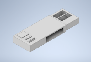
- Made some CAD ideas for the controls (but it looks more like an USB than a battery)
- Measured some controls dimensions
- Looked at how many buttons/switches we have (we have 6 LED rectangle buttons (4 are green) and at least 10 switches)
- We should use switches instead of buttons because we have more of them
- PS5 controllers were picked (talked with Calla & Peter); they are on the shopping list
- Found 2 orange 6' USB C cables [put on controls shelf]
- Put USB to Joystick board on shopping list (for broken switches)
1/17
Attendees: Sam, Sami, Tyler, Ben, Byers, Eric, Gabby
Work Completed:
- Added images of the controls ideas to the wiki
- Discussed the design of the controls
- Decided that the laptop height should be just tall enough to fit a power brick underneath
- Decided that the controllers should be on a stand to the right of the laptop
- Decided that the broken switches and LED toggle button should also be to the right of the laptop, in front of the controllers
- Decided that the bling should be on the inside of the top
- Decided that the top should hinge open instead of latch
- Decided that the top of the (closed) laptop should be about level with the surface of the controls
1/18
Attendees: Byers, Sam
Work Completed:
- Started making a CAD model for the design of the controls
- Controllers and broken switch joystick board came in
- decided on previous year's rocker broken switches; put on shopping list
- narrowed down the options for the solar panels
1/19
Attendees: Sami, Gabby, Sam
Work Completed:
- Add the overall concept drawing that Gabby did to the wiki, it's in the box on the controls shelf. Create a separate section with a description of the overall concept, most is captured in the notes from 1/17.
- Determine the overall size of the 9V battery style controls
- broken switches to the right of laptop
- these could be next to laptop or maybe something that flips out (we may not have height to have a drawer going under the laptop)
- Considered that the handles should be on opposite sides (one slightly above the other, so that both the top and bottom have handles)
- Considered that it may be better to have controller holders with a box shape, so that it isn't specific to the just PS5 controllers, can store other items, and would be easier to CAD.
- Looking at different handles (See design info for links)
- Decided that 4 of the the 5.35" x 4.33" ($8 each) solar panels would be the best ones to use
- Need to either design or find a design for the controller holders, there should be designs on the internet. (A sunken in box/bin)
- Decided that the hinge should be on the right and the latch should be on the left
- Looked at hinges and latches (See design info for links)
- Considered that the exterior terminals of the battery should be 3D-Printed parts and should be on the same side as the latches (but only attach to the bottom)
- Considered that the LED lights should run around the perimeter of the bottom (under the laptop) and across to the top, possibly in a pattern/design around the solar panels.
- Decided that at least somewhere on the design should say or allude to "1511 Volts"
- Considered decorating the top with 3D-printed parts that represent clean energy sources (wind turbine, hydroelectric, etc.) and outlining them with LED lights
- Decided not to have a "charge indicator on the side that discharges during the match"
- Considered that the exterior colors should be: black on the left and red on the right (side with the terminal), in the approx. proportions of a 9-volt battery.
- Started CAD design for the battery terminals (to 3D-print)
1/21
Attendees: Sam, Sami, Byers, Gabby, Eric, Tyler, Hailey
Work Completed:
- Considered that the solar panels should be for bling (only) and not be used to power anything
- Considered using silver hardware (handles, latches, hinges) so it will stand out
- Decided that the handles should be on the front side
- Looked in the closet for previous designs of handles, hinges, and latches
- Worked on the CAD for the controls (sheet metal)
- Put the handle and solar panels on the shopping list
- Decided to use a piano hinge
- Found piano hinge (and put on shelve in small closet)
- Worked on the assembly CAD for the controls and related items (laptop, controllers, etc.)
- Tested latch ideas
- Decided which latches to use
- Flushed out detail items remaining for CAD and 3D
1/22
Attendees: Sami, Gabby, Sam, Byers
Work Completed:
- Where will the bling on/off switch go? need to be accessible when top closed? (On the inside)
- Worked on the CAD for the controls interior
- Worked on the CAD for the controls exterior
- took motor out of a servo, added wires, and proved it will work with varying voltages
- Added all lettering, battery, and lightening bolt cutouts
- Made a prototype for the Arduino
- Added PEM studs for the controllers
Added PEM studs for the hinge
1/24
Attendees: Sam, Byers
Work Completed:
- Added PEM studs for the laptop
1/25
Attendees: N/A- Cancelled because of snow
Work Completed:
N/A- Cancelled because of snow
1/26
Attendees: Sami, Gabby, Sophia (had nothing to do, so helped Controls out)
Work Completed:
- Found different design ideas for windmill propeller (links in Design Info)
- Found more design ideas for controller stands (links in Design Info, organized into different categories)
1/28
Attendees: Sam, Sami, Gabby, Byers
Work Completed:
- Worked on the CAD for the battery terminals
- Worked on the CAD for the controls interior
- Re-named some controls CAD files with the correct part numbers
- added PEM studs for the hinge
- added through holes for handle
- Replaced spade terminals for broken switches and tested the board... its worked!
- Added PEM studs for the solar panels
- checked the spacing on the broken switches, the bezels don't overlap
- Ordered a 4-port USB hub
- Shop drawing of laptop stand
- Shop drawings of both exteriors
- Did the CAD for the controller holders and got that in the parts list
1/29
Attendees: Sami, Byers, Gabby, Eric
Work Completed:
- Shop drawings: .pdf and .dxf for laptop stand
- Shop drawings: .pdf and .dxf for controller top half
- Shop drawings: .pdf and .dxf for controls bottom half
- Soldered wires onto solar panels and tested them, they worked (produced about 5 volts under a phone flashlight)
- Added images of the CAD to this page
- initial circuit diagram
- created list of components needed for the bling board
- ordered perf board for Arduino
- tested to see what resistor values needed for the solar panels
1/31
Attendees: Sami, Sam
Work Completed:
- Create a(n) STP file for the top and bottom of the control box and have it sent to Amy or Eric. Here are directions for creating a stp file: Fabrication - .stp - 1511Wookiee (penfieldrobotics.com)
- Made an annotated version of the shop drawings to clarify information about the PEM studs.
- Moved items from "Not started" to "In Process"
2/1
Attendees: Sami, Eric
Work Completed:
- Created an Arduino Analog and Digital table (Above "To Do" List)
- Created a spread sheet for the Battery Terminals (Added visuals also) (Both in Design Info)
2/2
Attendees: Sami, Junias
Work Completed:
- Measured rough dimensions for a single solar panel: The longer side is about 5.351 inches and the smaller side is about 4.325 inches
- NOTE: when we went into the small closet we only saw 3 out of 4 solar panels.
2/4
Attendees: Sam, Sami, Byers
Work Completed:
- Controls sheet-metal parts arrived
- Cleaned and filed the sheet-metal parts
- Drilled holes for latches and handle
- Put together controls, and took apart
- Started Painting the sheet-metal parts
- validated the Arduino pinout - had to tweak it
- updated test Arduino code
2/5
Attendees: Sami, Sam, Eric, Byers
Work Completed:
- Continued spray-painting the sheet-metal parts
- Worked on the CAD for the battery terminals
- Worked on the CAD for the controllers holder
- Worked on shop drawings for the battery terminals and controllers holder
2/7
Attendees: Sam, Sami, Gabby, Eric, Junias, Junias’s Dad
Work Completed:
- Changed the STL files of P141 and P142 to millimeters, and printed the shop drawings
- Added pictures of controls to wiki
- Made CAD concept for a cable retention scheme
- Measured the Arduino, Velcro, and Solar Panels to determine the height of the solar panels platform
- Created a CAD that represents the Solar Panels and the space their wires take up
- Started CAD for the solar panels platform
2/8
Attendees: Sami, Sam, Gabby, Nick L., Olga, Hannah, Duffy
Work Completed:
- CAD for solar panel mount was finished and is now in queue for getting 3d printed
- Added holes in the solar panels platform for a switch and a button (dimensions might be off)
- Made the solar panels closer together on the platform
- Put handle and spacer on (secured and not flexing)
- locked laptop stand in
- piano hinge and 1/2 of the latches put in
- Duffy made a list of questions, speak to Duffy
2/9
Attendees: Gabby, Junias, Junias's Dad
Work Completed:
- Connected wires to two prong connectors on Arduino board
- Continued to work on soldering power MOSFET connecters.
- Added resistor to Arduino board (which is going to be attached to LED's)
- Added the lock nuts to the computer stand
- Decided on not making a cable retention thing because the USB cords are strong enough (you can hold the controller by the cord and shake and it will not unplug) and there is no accurate cad for a ps5 controller
2/11
Attendees: Sam, Gabby, Byers, Sami, Eric
Work Completed:
- Worked on the CAD for the solar panels platform
- Decided that the LEDs button and switch should be on the side of the solar panels platform, instead of on the top
- Added the controllers holder into the assembly CAD
- Changed the rotation of the solar panels in the CAD
- Finished the CAD for the solar panels platform, made shop drawings, and exported the STL
2/12
Attendees:
Work Completed:
2/14
Attendees:
Work Completed:
2/15
Attendees:
Work Completed:
2/16
Attendees:
Work Completed:
2/18
Attendees:
Work Completed:
2/19
Attendees:
Work Completed:
2/21
Attendees:
Work Completed:
2/22
Attendees:
Work Completed:
2/23
Attendees:
Work Completed:
2/25
Attendees:
Work Completed:
2/26
Attendees:
Work Completed:
2/28
Attendees:
Work Completed:
3/1
Attendees:
Work Completed:
3/2
Attendees:
Work Completed:
3/4
Attendees:
Work Completed:
3/5
Attendees:
Work Completed:
3/7
Attendees:
Work Completed:
3/8
Attendees:
Work Completed:
3/9
Attendees:
Work Completed:
3/11
Attendees:
Work Completed:
3/12
Attendees:
Work Completed:
3/14
Attendees:
Work Completed:
Controls Rules 2023
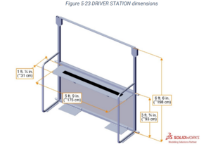
DRIVER STATION
Height of driver station shelf from floor: 3ft .75in (36.75) inches
Total height of driver station: 6ft 6in (78 in)
Maximum size controls: 78 - 36.75 = 14" deep x 60" wide x 41.25" tall
9.9 OPERATOR CONSOLE
R901 *Use the specified Driver Station Software. The Driver Station Software provided by National Instruments (install instructions found here) is the only application permitted to specify and 9 ROBOT Construction Rules V2 109 of 141 communicate the operating mode (i.e. AUTO/TELEOP) and operating state (Enable/Disable) to the ROBOT. The Driver Station Software must be version 22.0 or newer.
R902 *The OPERATOR CONSOLE must have a visible display. The OPERATOR CONSOLE, the set of COMPONENTS and MECHANISMS used by the DRIVERS and/or HUMAN PLAYERS to relay commands to the ROBOT, must include a graphic display to present the Driver Station Software diagnostic information. It must be positioned within the OPERATOR CONSOLE so that the screen display can be clearly seen during inspection and in a MATCH.
R903 *Connect FMS Ethernet directly to the OPERATOR CONSOLE. Devices hosting the Driver Station Software must only interface with the FMS via the Ethernet cable provided at the DRIVER STATION (e.g. not through a switch). Teams may connect the FMS Ethernet cable to the device running the Driver Station Software directly via an Ethernet pigtail, or with a single-port Ethernet converter (e.g. docking station, USB-Ethernet converter, Thunderbolt-Ethernet converter, etc.). The Ethernet port on the OPERATOR CONSOLE must be easily and quickly accessible.
[Teams are strongly encouraged to use pigtails on the Ethernet port used to connect to the FMS. Such pigtails will reduce wear and tear on the device’s port and, with proper strain relief employed, will protect the port from accidental damage.]
R904 *OPERATOR CONSOLE physical requirements. The OPERATOR CONSOLE must not
A. be longer than 5 ft. (~152 cm)
B. be deeper than 1 ft. 2 in. (~35 cm) (excluding any items that are held or worn by the DRIVERS during the MATCH),
C. extend more than 6 ft. 6 in. (~198 cm) above the floor, or
D. attach to the FIELD (except as permitted by G301).
R905 *FIELD wireless only. Other than the system provided by the FIELD, no other form of wireless communications shall be used to communicate to, from, or within the OPERATOR CONSOLE.
[Examples of prohibited wireless systems include, but are not limited to, active wireless network cards and Bluetooth devices. For the case of the FIRST Robotics Competition, a motion sensing input device (e.g. Microsoft Kinect) is not considered wireless communication and is allowed.]
R906 *No unsafe OPERATOR CONSOLES. OPERATOR CONSOLES shall not be made using hazardous materials, be unsafe, cause an unsafe condition, or interfere with other DRIVE TEAMS or the operation of other ROBOTS.


