2024:Electrical Main
Known Devices
List of devices that have been established by the various mechanism groups
Sensors
| Device |
Mechanism |
Detail |
Wiring notes |
|
Diffuse retro-reflective sensor |
Gamepiece - Intake |
Senses gamepiece |
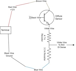
Wire for Dark operating 12V powered Voltage divider added to cable pigtail See circuit diagram below |
|
Rev through-bore encoder |
Gamepiece - arm |
Used in absolute position mode to indicate arm pivot angle. |
5V powered |
|
Leaf lever limit switch |
Hang - brake |
Triggers when pawl on brake is fully lifted and clear of ratchet wheel |
roborio DIO |
|
4x CANcoder
|
Drivebase
|
One per swerve module. Indicates pivot pointing of wheel
|
|
|
|
|
|
|
Motors and Actuators
| Device |
Mechanism |
Detail |
Wiring notes |
|
8 x NEOs |
Drive |
Swerve modules, one each corner of robot, each using 1 NEO for pivot and 1 NEO for propulsion |
|
|
NEO 550 |
Gamepiece - intake |
Runs intake to pull in or eject a game piece |
|
|
2 x NEOs |
Gamepiece - shooter |
Runs shooter wheels.
One NEO for top set of wheels
One NEO for bottom set of wheels |
|
|
NEO
|
Gamepiece - arm
|
Pivots arm
|
|
|
NEO 550
|
Gamepiece - arm
|
Actuates bicycle brake for arm pivot
|
|
| 2 x NEO |
Hang |
One NEO per hanging arm (one left, one right) Causes hang hook to go up or down |
|
| 2 x electric solenoid |
Hang |
Actuates braking pawl against ratchet wheel. One solenoid per arm brake (one left, one right) Energizing lifts the pawl off the ratchet wheel. Integrated spring pushes pawl into ratchet wheel |
Both solenoids controlled via one SPIKE relay (one on M+ and one on M- with common ground) |
Circuit diagrams
Allen Bradley 42EF-D2MPAK-F4
Daily Status
' 1/20/2024
- Disassembled old batteries
- Assembled our 13 new batteries (yay!)
- Wired the prototype Game Piece mechanism for testing
- Wired the temporary test board for the new drive base for Programming to create/test swerve drive code
1/21/2024
- Spike Relay Vex wired for solenoids on hang
1/27/2024
- Updated IO Map per the Known Devices section - we should really update the PDH connections to be logical per the physical layout (see below)
- Terminated 2x solenoids for hang ratchet/pawl mechanism
- Investigated Solenoid/Spike Relay module, cleaned up solenoid-side terminations
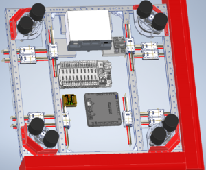
- Started initial layout of major control system components (\\penmediafs01\robotics$\2024\02 Build Season\01 Final Robot Assembly\A002 Drive Base Assembly Electrical.iam)
1/28/2024
- Tested several sensors for performance using 3M reflective silver tape. Foil tape isn't as reliable and prone to damage. While testing sensors were powered with 7-12 volts.
- OPB720A-06Z Reflective Sensor:
- Not Tripped: Signal voltage depended on the amount of voltage inputed for power
- Tripped: Fluctuating signal voltage
- Results varied between trials, seems unreliable
- EE-SPY415 Photomicrosensor (Reflective):
- Not Tripped: Fluctuating signal voltage
- Tripped: 0.003V
- Range: 0in - ~12in
- Interesting that the voltage kept increasing while reading the signal not tripped
- 42EF-D1MNAK-A2 Diffuse Sensor
- Not Tripped: 0.73V
- Tripped: 1.0V
- Range: 0.5in - >20in
- OPB720A-06Z Reflective Sensor:
- Looked into similar banners online
- Q20ND Diffused Sensor 25cm range NPN $104 AndyMark

