2015:Electrical Controls Subteam
Design
To provide for narrower controls for transport, driver #1's side of controls (i.e. 2 joysticks) will slide to the right and cover the laptop. These will automatically lock.
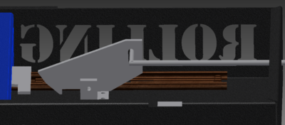
The intent is to have a simple release mechanism. When released a gas strut will automatically open the controls.
- 2 joysticks for main driver
- 1 joystick for aux driver
- 1 3-way toggle for autonomous (up=a pre-picked auto-mode; center=no auto; down=use auto-mode that is selected on Dashboard)
- 8 broken switches
- Laptop for Dashboard
- Robot IO Map
Renderings

|

| |
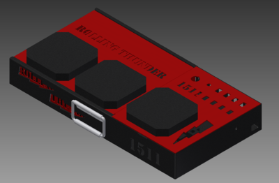
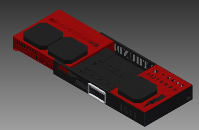
| This is the controls closed. | This is a picture of the controls open. | |
 |
||
| A close up of the latch design (located underneath the aux panel) | ||
 |
||
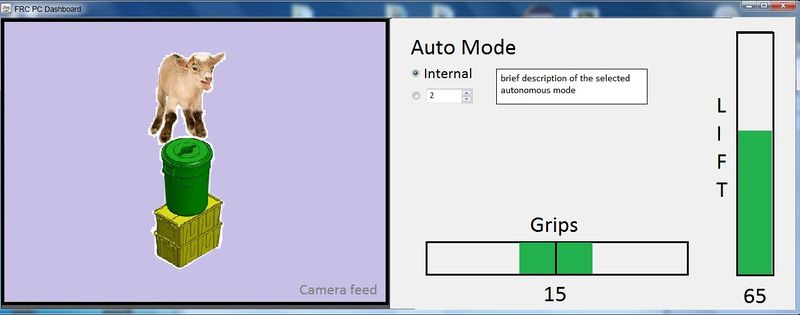
| Dashboard layout |
||
Tasks
| Status |
Task | Information (decisions are in bold) | Owner |
| On hold |
Lights |
because there is limited space within the controls this year, this is on hold until the wiring and placement of power is mocked-up |
|
| Started |
LaunchPad |
|
Andrew |
| Started |
Wiring | if lid is here, use that; otherwise print the drawing to use a mockup. determine length of ribbon cable to go from LauchPad to all switches | Gunnar |
| Complete |
Latch mount |
|
Alyssa |
| Complete |
latch handle |
needs to be designed orded knobs from McMastercarr |
Chris |
| Started |
power cable |
for now, we added a cut-out in sheet metal for the snap-in plug we already have. if we find we have space and can get a used iron, we may use that instead |
|
| Completed | Setting up the development environment on a new computer |
Download these items:
|
|
| Completed |
ethernet port location |
will use port plug we already have and put it on the right top |
|
| Completed |
select board for joystick interface |
will use the LaunchPad |
|
| Completed |
General design for latch |
|
|
| Completed |
determined handle to use | will use one handle on front (no one liked having them on the ends). part is here |
|
| Completed | determined switches |
will use 3-way toggles and square rockers for broken switches. parts are here | |
| Completed |
LaunchPad |
|
|
| Completed |
Latch design |
|
Chris |
| Completed | sheet metal drawings for boxes | these have been sent to Harris. there were some issues. those were fixed and drawings resent. waiting for part | |
| Completed | sheet metal drawings for top |
this has been sent to Harris. drawings approved. waiting for part |
|
| Completed |
sheet metal drawings for laptop | this has been sent to Harris. drawings approved. waiting for part |
|
| Completed |
Fabricate parts |
|
|
| Completed |
Data sheets |
get data sheets for all parts being used and place in Controls folder |
|
| Completed |
Dashboard |
need to determine what goes on the Smart Dashboard and lay it out We will have large camera feed with the gripper and lifter gauges on the botton and side (see picture in Design section above). We need to talk to strategy about 1 or 2 camera feeds |
Chris, Andrew, Mr. Byers |
| Completed |
Color scheme |
The Sliding panel and the aux panel are red. The base and all internal parts are black. |
All |
Meeting Minutes
1/6 (Chris, Mr. Byers)
- discussed preliminary options
1/7 (Chris, Mr. Byers)
- discussed preliminary options
1/8 (Chris, Mr. Byers, Eric, David M.)
- selected overall concept (sliding controls)
1/10 (Gunnar, Alyssa, Andrew, Eric, Mr. Byers, David M.)
- inventoried parts we have
- determined controls we thought were needed
- went over desires from strategy team
- Home Depot shopping run
- met with Elliot to select secondary controls
- created wiki page
- created todo list
1/11 (Alyssa, Andrew, Mr. Byers)
- investigated latch options
- investigated retractable cords
- selected board for controls
1/13 (Chris, Eric, Mr. Byers, Gunnar, Andrew, Alyssa, Dave, Frank)
- Chris worked on the main base and assembly
- Gunner worked on the very complicated drawer slides
- Alyssa and Andrew worked on the Aux panel
- Eric found a gas shock that will fit our needs
- Attended integration meeting rom 6:30 to 7:00
1/14 (Chris, Mr. Byers)
- Chris updated assembly
- changed laptop mount so we have more space between it and the sliding lip
1/15 (Chris, Eric, Alyssa, Dave, Frank)
- Chris worked on the main base and assembly
- Alyssa worked on the lightning bolt cutout
- Eric found three way and broken switches and got them along with the gas shock on the shopping list. Datasheets are located in a datasheet folder with the rest of the controls stuff.
- Attended integration meeting rom 6:30 to 7:00
1/17 (Chris, Andrew, Gunnar, Alyssa, Dave, Eric, Mr. Byers)
- Chris worked on finishing the final assembly and the latching mechanism
- Gunnar worked on cadding up some of the electrical components, looking up some possible latches, and cadding other random parts.
- Andrew worked on the final drawings with Chris, finalizing the aux panel, placement of words, figuring out the hinge situation, and looking up other important information
- Alyssa worked with Andrew with his tasks as well as finalizing the lightning bolt cut out
- Eric and Mr. Byers assisted the students with their tasks, and kept them on task and at work.
- Attended integration 6:30 - 7:00
- Met the deadline for the design
1/18 (Andrew, Chris, Alyssa, Eric, Mr. Byers)
- Finalized all of the parts
- Made all of the drawings for the parts
- Sent the parts out
- Secured a extension cable for the inside of the controls
1/20 (Andrew, Chris, Alyssa, Mr. Byers, Eric)
- Fixed incorrect drawings and resent them to Harris
- Completed one of the drawings to be made in our shop
1/21 (Andrew, Chris, Mr. Byers)
- Andrew worked with the development board and downloaded the software to the laptop that will be used in this years controls
- Chris worked with Mr. Byers and updated the io map for the joysticks; talked with Elliot too, to make sure we mapped the buttons the way he wanted.
1/22 (Chris, Gunnar, Eric, Mr. Byers, Dave)
- Chris worked with Mr. Byers and Mr. Cavaliere to get a bushing for the release mechanism
- Gunnar worked with Eric to create schematic for switches to LaunchPad
- Mr. Byers and Dave connected the LaunchPad and loaded the supplied HID firmware; and verified buttons worked
1/24 (Chris, Gunnar, Alyssa, Andrew, Mr. Byers, Dave)
- Andrew got LaunchPad environment loaded, sample build and working, and updated sample to match our button map
- Gunnar started wiring for LaucnhPad
- Chris finalized the drawings to be made in the shop.
- Printed all of the drawings and put them in the shop
- Worked with Dave S. to order more crimp terminals that are needed to connect to the broken switches and 3 way switch.
- Alyssa assisted the shop with building drivetrain parts.
1/25 (Chris, Mr. Byers, Gunnar, Alyssa)
- Added a picture to the rendering section of the wiki detailing the latch design.
- Decided on the color scheme, and uploaded pictures.
- Mr. Byers and Chris worked on the smart dashboard design in MS Paint.
- Chris manufactured some of the parts, and Alyssa did the others
- Gunnar worked on the electrical part that goes underneath the aux panel
- Gunnar did what he could with the ribbon cable while he waits for the rest of the terminals.
- Gunnar started work on the perf board to connect to the microcontroller
- Chris painted the parts that had been manufactured.
1/27 (Chris, Andrew, Mr. Byers, Eric, Gunnar, Alyssa)
- Andrew and Mr. Byers figured out how to remove the joystick functions. Also cleaned up code.
- Eric brought in some parts from Harris (Laptop cradle, Aux panel)
- Chris worked with Gunnar and Alyssa to paint the laptop cradle.
- Chris showed Alyssa how to spray paint properly, then let her and Gunnar finish
- Gunnar worked on parts of the electrical
1/28 (Chris, Mr. Byers, Alyssa)
- Chris worked with Mr. Byers to drill the holes ion the aux panel for the joystick.
- Chris painted the aux panel red, according to the color scheme that we agreed on
- Alyssa helped machine parts needed for the robot
- Chris cut the hinge for the aux panel to size with the help of Mr. Byers and Alex
1/29 (Chris, Mr. Byers, Gunnar, Alyssa)
- Gunnar worked on putting the elecrical components into the aux panel. (broken switchs, 3 way switch, ethernet port)
- Gunnar soldered a ethernet wire to the ethernet breakout board and tested it
- Alyssa worked on machining parts for the robot
- Chris worked on organizing the controls box
- Chris helped Gunnar with his tasks
1/31 (Chris,