2016:Lifter: Difference between revisions
Programming (talk | contribs) No edit summary |
|||
| Line 30: | Line 30: | ||
* One Retroreflective sensor (Omron EE-SPY415) to determine when the scaler is at its high end stop. | * One Retroreflective sensor (Omron EE-SPY415) to determine when the scaler is at its high end stop. | ||
* One Optical Flag sensor (OPB815WZ) to determine when the scaler is at its low end stop and home for encoder. | * One Optical Flag sensor (OPB815WZ) to determine when the scaler is at its low end stop and home for encoder. | ||
* One Shaft Encoder (GrayHill 61KS256) for use to measure scaler extension location. This is mounted on the lift/lower drive shaft | * One Shaft Encoder (GrayHill 61KS256) for use to measure scaler extension location. This is mounted directly on the lift/lower drive shaft | ||
= Scaler Pivot Arm = | = Scaler Pivot Arm = | ||
Revision as of 09:29, 4 February 2016
The Plan
We have come to the conclusion that the best method of scaling the castle near the end of the match is using a telescoping arm to latch onto the bar and then lift with the arm.
Arm Extension and Lift
Motors
- Two 775pro motors
- versaplanetary 50:1 with two motor adaptor
- 12 tooth on motor shaft to 12 tooth on mechanism.
- 40A breaker for each motor
- Calculations:


Locking Mechanism
This is used to keep the arm locked in the retracted position (for when the robot is lifted in the air). The current plan is to use a ratcheting mechanism on the extension/lifter drive shaft:
- Ratchet gear - has teeth inclined slightly tangental in a uniform direction around the gear
- Pawl - a solid block which engages the teeth in the above gear, preventing the gear from spinning in one direction (in our case, the direction that would allow the scaler arm to extend/the robot to fall!)
- Hightec HS322-HD Servo - used to lift and lower the Pawl. This should be lifting the pawl during arm extension and lowering it during retraction when lifting.
The pawl engagement is such that the servo CANNOT lift it back up again once the ratchet has back-pressure on it (from the robot being in the air, or whatever). However, if necessary, the pawl can be disengaged by having the servo trying to lift it and then turning the ratchet gear slightly in the arm retract/robot lift direction.
Sensors
- One Retroreflective sensor (Omron EE-SPY415) to determine when the scaler is at its high end stop.
- One Optical Flag sensor (OPB815WZ) to determine when the scaler is at its low end stop and home for encoder.
- One Shaft Encoder (GrayHill 61KS256) for use to measure scaler extension location. This is mounted directly on the lift/lower drive shaft
Scaler Pivot Arm
Motors
- VeX BAG motor
- Use Versaplanetary 100:1
- 12 tooth sprocket on motor shaft driving a 42 tooth sprocket
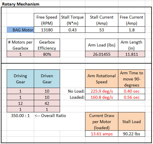

Sensors
- Two Optical Flag sensor (OPB815WZ) to determine when the arm is at an end stop -- NOTE: due to switch to potentiometer for absolute positioning, these may be removed!
- One potentiometer to determine where the arm of the scaler is. This is mounted into a gear which mates to another gear on arm pivot. The gearing is NOT 1:1 (XXX - need gear ratio here)
Update 1/26/16
3.1 What we're working on
- Design rollers/stops for the arm stages
- Design lightning holes
- Design motor mountings and figure out how to attach to the drivebase
- Send parts to chamtek
- Finish CAD work
3.2 Photos
This is the hook we will be using.

This is the actual arm we designed.


Update 2/2/16
- Scaler assembly put into shoulder assembly and placed into the final robot assembly
- Still many changes to make, see robot design to-do list -> https://docs.google.com/spreadsheets/d/1hz4oDlifcAY6ZzfIxCHKYLpOIuN3yy11fZVJu-tDZ0U/edit
- Picture of shoulder assembly in current state v


Update 2/3/16
Performed stress test in Inventor on the ratchet and pawl for the scaler.
Worked on ratchet and pawl design.

Current design 2-3-16 ^