Calculations for the drive base perimeter and diagonal distance based on constraints from strategy and various subteam leads. Refer any questions to Nick L. or Berkeley P.

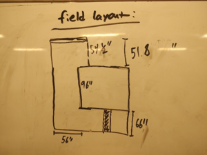
A basic sketch of the field including the community and charging station. For the double labled dimension, 51.8 is the length from the edge of the barrier base to the edge of the charge station. However, we later found that there is more space here if measured from the lexan to the charge station, effectively 59 inches.
The minimum distance for the drive base diagonal is therefore 56 inches. Strategy requested a minimum of a 27 inch side with bumpers, 20.5 without. The intake subteam requested a minimum of a 30.5 inch side with bumpers, 24 without. These are the major constraints we worked with. Bumpers add an additonal 3.25 inches to each side, for a total of 6.5 extra inches.

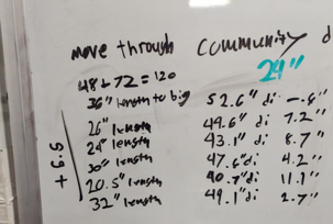
Below are the calculations for a drive base with a width of 24 inches without bumpers, and a variety of lengths. The left column is the side length without bumpers, the middle column is the diagonal distance with bumpers, and the right column is irrelevant.

More qualitative drive base constraints
Based on our calculations, driver input, subteam and strategy requirements, and mentor approval, we decided to use a 26.25 inch by 30.25 inch drive base WITHOUT bumpers, and 32.75 inch by 36.75 inch WITH bumpers. This allows us to have a diagonal of 49.225 inches, and a minimum extra distance of 6.775 inches while in the shortest part of the community. Additionally, a 12 inch by 10 inch square bumper cutout is necessary for intake.

Some extra calculations for a 26 inch by 24 inch drive base without bumpers.
1/17/2023
Drive base length has changed to 32.25 inches, at the request of the Lift subteam (They wanted 38 or 36 to feel good, but this would make the robot HUGE). Additionally, we have explored the suggestion to make cutouts in the central C-channel and make the drive base width 2 inches smaller. We have a working CAD of this model, but with a cylinder representing the movement of the swerve modules, and the 2 inches of width removed.

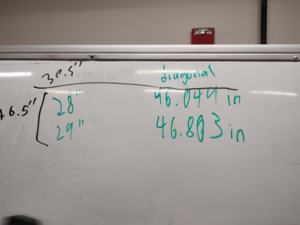
Additional calculations for drive base with 28 inch and 29 inch length with a 24 inch width, excluding bumpers. Diagonal lengths include bumpers.


