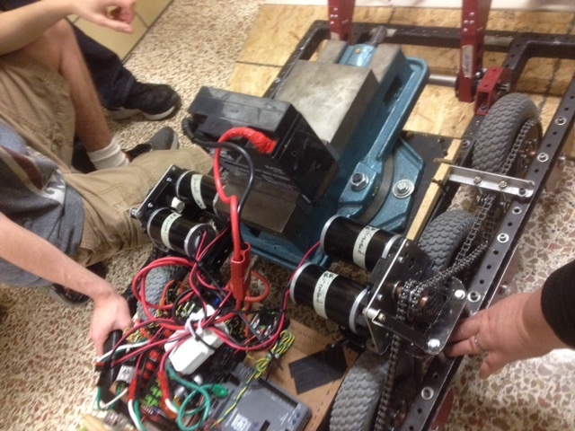
2016:Drivetrain
12/21/2016 Frame information
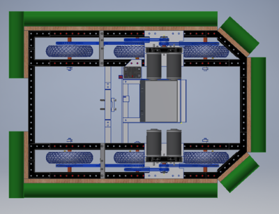
- drive base dimensions: 25" wide x 37" long
- Front is straight across
- Rear is 16" straight
- Both ends are chamfered 4.5" width x 5" length
- 6 wheel design with pneumatic tires
Wheel spacing is 9.5" between wheels- Wheel spacing is 11-1/2" center-to-center
Wheel axles are 9 inches from each end- Wheel axles are 7 inches from each end. Rear tires are less than 1/4" from the rear drivebase frame!
- Center wheel dropped 1/4 inch
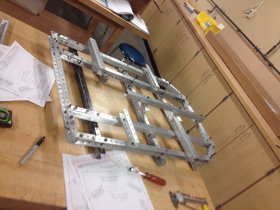
- Frame construction is "c-channel" and 1.125 wide x 1.250 tall and will be a welded construction
- We tested a frame mock up over all the defenses. The comment is the Cheval de Frise will require a belly pan
- The moat will require a chamfer on the bottom edge of the rear and front members
Transmission
- CIMple box from Andy Mark 12 x 56 tooth (4.167:1 reduction)
- Speed sensor will be mounted on the Cimplebox encoder take-off
- The secondary reduction will be 12 x 36 tooth for a 14:1 overall reduction
- the design wheel speed is 10.29 ft/s loaded
- (We are considering mounting the drive chains on the outboard side of the wheel channel to create more space in the center of the robot)
- The chain from the 36T front wheel sprockets will be routed around a high idler to keep it away from obstacles between the wheels.
Bumpers
- Scaling team requested bottom edge of bumper height to be 5 1/4" off the floor
Gyro
- Analog Devices ADW22307 1-axis Analog Gyroscope
Battery Box
- Battery box design is forthcoming. Placement may be able to help tune the robot CG, depending on the placement of the other robot mechanisms/systems.
Update Saturday 1/23/2016
- Continued drivebase frame CAD work.
- Added retail parts to the z-CAD library
Update Sunday 1/24/2016
- CAD design of wheel blocks
- Added chain to CAD model
- Completed CAD design of the Idler Support Block
Update Tuesday 1/26/2016
- Continued CAD work for the drive base.
- Added bumpers to drivebase CAD design
- Completed enough of the drive base to submit it for inclusion in final assembly
Update Wednesday 1/27/2016
- Fabricated the drive base frame
- Generated drawings for transmission mounting platform
- Generated drawings for drive base assembly
Update Thursday 1/28/2016
- Cut the transmission mounting platform spacers
- Cut the copper spacers for the wheels
- Fabrication of the drivebase transmission mounting platform
- Cut the front C-channel angles for the drive base frame.
- Prepared the drivebase frame for welding
- Delivered the frame to be welded at 8pm.
Update Saturday 1/30/2016
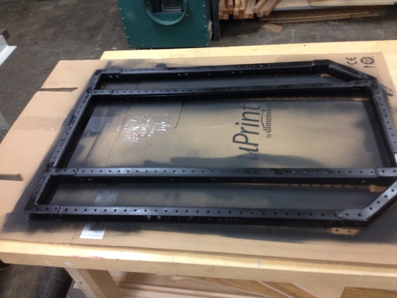
- Drive base returns from the welder. Thank you Dave Drelick for a fantastic job!
- Filed the drive base and painted it (black).
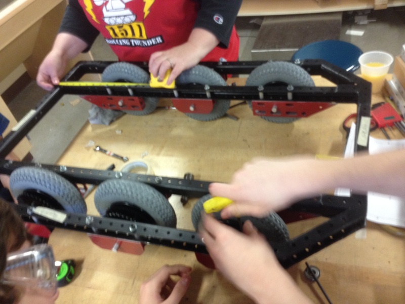
- Painted the Wheel blocks (red).
- Assembled the wheel blocks onto the drive base frame
Update Sunday 1/31/2016
- Assembly of the transmission mounting pads. Had to reassemble several times due to several issues:
- Chain clearance cutouts had to be widened
- Spacers were different heights and had to be "graded" to get enough of approximately the same height
- One wheel was assembled with the wrong spacer and had to be redone.
- Chained left side of robot. Discovered that the idler sprocket bracket does not have enough adjustment for chain tensioning.
Wheel Idler does not have chain tensioning adjustment range. We forgot to account for the nut!
Update Tuesday 2/2/2016
- Assembly of the the drivebase continued.
- Completed chaining of the drivetrain.
- Added shaft encoder to the CIMple box transmission.
- Finished fabricating blocks for the idler redesign. The fabrication did not go well: tapped holes were too big, blocks did not have clearance to pass the tires, and alignment of the axle in the blocks proved almost impossible. We shaved an angle off the blocks to fit around the wheels, but no one expects this to be the final design. So back to the drawing board.
The robot drivetrain was weighed: 45 lbs
The drivetrain is tight. Speculation is that the problem is not chronic--it is probably due to chaining too tight, wheel spacers too tight, and possibly gearbox not broken in.
Update Wednesday 2/3/2016
- Assembly of the drive base continued.
- Updated the wiki
Wheel Idler Block Modification
The original from wheel chain idler block did not permit enough adjustment for proper chain tensioning. The second design was too difficult to adjust and came too close to the wheels. The third design idea is to hang the idler from a block across the wheel channel by I-bolts.
Update Thursday 2/4/2016
- Fabricated the new front wheel idler sprocket assembly and installed it on the robot.
- Inspected the drive base for areas that we can save weight:
- Removed material from the transmission platform. Satrting weight, 0.54lbs, and ending weight, 0.38lbs
- We will replace steel idler sprocket and axle with aluminum.
- Screws and nuts weigh a lot! We are considering replacing the full channel length 1/4-20 screws on the wheel blocks with shorter with short screws and no spacers.
- Mocked-up the skid plate that will protect the robot undercarriage from damage.
The new drive wheel idler is very good. It is lighter, smaller, and easy to adjust. Win!
Update Friday 2/5/2016
Machine Shop Maintenance day.
- Cleaned up wood box: Recycled useless scap, and removed sawdust
- Cleanup up empty box storage area: recycled lots of cardboard
- Resorted drill bits and organized the drill boxes
Update Saturday 2/6/2016
- Added brace to the CIMple box transmissions to the transmission mounting platform
- Added the electrical board to the robot drive base
- Drove the robot!
Update Sunday 2/7/2016
- Started thinking about C-channel parts for Robot 2
- Continued drive testing the drivebase
Found problems with the robot negotiating two of the target game obstacles: The Moat and the Ramparts
- The Front and Rear of the robot impact the Rampart above the C-channel and damages the bumper
- The robot can get stuck in the moat, requiring a great deal of luck and effort to get free.
These problems are serious enough to possibly require redesigning major robot drive base systems....
Update Tuesday 2/9/2016
This day was dedicated to solving the drivebase issues.
- Fabricated new angle blocks to try to solve the problem with the robot failing to drive out of the Moat.
- Two designs were tried:
- A sharp angle to 3/4" below the wheel block
- A gradual angle from the frame perimeter to the wheel block.
- Neither design solved the problem.
The next attempt will be to widen the wheel spacing on the front wheels from 9-1/2" to 11-1/2" to prevent both wheels from being in the Moat simultaneously.
Update Wednesday 2/10/2016
Marathon session to get the drivebase geometry figured out.
- Started work session by creating a staggered wheel configuration:
- The left side wheels were all moved 2 inches toward the front of the robot
- Testing showed that the robot di not remain straight to take advantage of the stagger, but went sideways instead.
- Driving in a straight line became very challenging
- Entertained many ideas about how to reconfigure the wheels
- Ended the work session by creating a symmetric wheel geometry with the wheels moved from 9-1/2" separation to 11-1/2" separation:
- The robot still has a hard time surmounting and exiting the moat, but it does not get stuck.
- The robot traverses the other obstacles quite well
Thankfuly, we ended the session with a good configuration, and did not have to give up any of the breacher obstacles. Thought for today: "The road to success is paved with broken tie-wraps"</div>
Update Thursday 2/11/2016
- Updated drivebase CAD model to reflect new wheel spacing
- Cut overhanging wheel blocks to fit rear of robot.
- Surrendered robot to breacher team so that they could add breacher mechanisms and do tests
Drivebase still needs undercarrige skid pan</div>
Update Saturday 2/13/2016
- Updated CAD model to include new front wheel idler idler
- The Drivetrain is now in the hands of the other teams. Electrical parts and breacher mechanisms are being installed
- The team is helping with fabrication and installation of the rest of the robot!

