2019:Controls: Difference between revisions
Programming (talk | contribs) No edit summary |
No edit summary |
||
| Line 111: | Line 111: | ||
*download program: Actions -> Program | *download program: Actions -> Program | ||
</div> <div class="mw-parser-output"><div class="mw-parser-output"><div class="mw-parser-output"><div class="mw-parser-output"><div class="mw-parser-output"><div class="mw-parser-output"><div class="mw-parser-output"><div class="mw-parser-output"> | </div> <div class="mw-parser-output"><div class="mw-parser-output"><div class="mw-parser-output"><div class="mw-parser-output"><div class="mw-parser-output"><div class="mw-parser-output"><div class="mw-parser-output"><div class="mw-parser-output"> | ||
<div class="mw-parser-output"> | |||
<div class="mw-parser-output"> | <div class="mw-parser-output"> | ||
= Meeting Minutes = | = Meeting Minutes = | ||
| Line 157: | Line 158: | ||
Attendees: Adrian, Aidan, Devon, Jadon, Tanner, Eric | Attendees: Adrian, Aidan, Devon, Jadon, Tanner, Eric | ||
Work Completed: Edited original concept for the control board by replacing the computer for a bigger one that was needed. Control board is official codenamed the “Cash Register” (or CR). A CAD design was started for the base of the CR along with a to scale model of the computer we will be using. Only the Bottom, front and back of the base is “finished”. The sides | Work Completed: Edited original concept for the control board by replacing the computer for a bigger one that was needed. Control board is official codenamed the “Cash Register” (or CR). A CAD design was started for the base of the CR along with a to scale model of the computer we will be using. Only the Bottom, front and back of the base is “finished”. The sides may be a seperate piece for easier assembly and the Front Plate is in prototype. CADed the USB HUB, made sure datasheets were pulled into this year's folder. Started to gather some of the parts and put them into the new tackle box. | ||
<span style="font-size: large;">1/16</span> | <span style="font-size: large;">1/16</span> | ||
| Line 299: | Line 300: | ||
<font size="4">2/17</font> | <font size="4">2/17</font> | ||
Attendees: Work Completed: </div> </div> </div> </div> </div> </div> </div> | Attendees: Work Completed: </div> </div> </div> </div> </div> </div> </div> </div> | ||
</div> | </div> | ||
Revision as of 14:27, 16 January 2019
Overall Concept
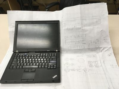
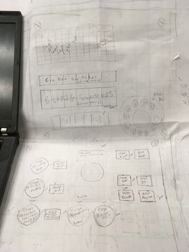
- Apollo mission control look. See https://imgur.com/gallery/HIAW6. Concepts sketched out in the Controls notebook.
- A rotary phone dial needs to be included.
- Could include a dial counter for match time remainng, similar to https://www.indiamart.com/proddetail/electrical-counter-3385933755.html
- Need the silver handles on each side of the laptop display.
- Status lights and broken switches in "matrix".
- Need to also include the panel thumbscrews.
- Control box will not fold. Laptop remains open at all times, screen will be 'covered'.
- Laptop on left.
- Secondary controls on 'bottom' right.
- Broken switches and bling on 'top' right (all are latching and illuminated)
- Power, ether and extra USB on left side.
- 'Door' on left side to store Xbox controller. Controller will always be plugged in.
- Handle on top for carrying; or can carry by holding from bottom
- May need to include some additonal stuff for camera display during the sandstorm.
- XBox controller for the primary driver
- Secondary driver controls (all buttons are momentary, all non-cargo are illuminated):
- Elevator presets:
- 3 hatch for rocket
- 3 cargo for rocket
- 1 cargo for cargo ship
- 1 cargo for driver station
- Arcade style joystick for manual override of elevator presets
- 2 buttons for cargo intake & outtake (programming will automatically bring arms in)
- 2 buttons for hatch retain/release (programming will automatically bring arms out)
- 2 buttons for hab front/rear [this might be on primary driver's controller]
- Elevator presets:
- Design:
- space buttons 1cm apart; 2cm from left and right edges
- Try to make USB for Xbox controller accessible for post season use
To do
Not Started
- Get/create models for joystick.
- CAD for outer case
- CAD for secondary driver panel. spacing is on the full scale model. 1cm between most buttons. 2cm from edges of panel that screws in.
- Continue to develop the concept of the controls.
- How will the laptop sit in the controls and open.
In Process
- create model of the controls laptop. Need to have a model of the laptop partially open.
Completed
- Not doing with clamshell design
- Picked: buttons, joystick, thumbscrews, handle
Useful Links
- Subteam Student/Mentor Photos
- Zero Delay USB Joystick Encoder
- Joystick Controller Board
- Analog Slide Position
- Example push buttons (need to make sure we pick ones that stay pushed; are not momentary):
PSoC Install (for lights)
PSoC Creator IDE
Download latest "PSoC Creator" from Cypress (http://www.cypress.com/products/psoc-creator-integrated-design-environment-ide) and install it (use Typical install; at end run Updater and maek sure you have the latest stuff)
For user name and password, you can use: mailme@mailinator.com mailme123
Toolkits and Board Driver Install
Get controls2018 from SVN
Run: vcredist_x86.exe
Run: USBSerialSDKSetup.exe (do Typical install; at end run Updater and maek sure you have the latest stuff)
Run: CY8CKIT04942xxSetupOnlyPackage_revSA.exe (do Typical install; at end run Updater and make sure you have the latest stuff)
While you press and hold the SW1 Prog button on the cypress board, plug in the USB cable to the PC (it will take a while for it to install 5 drivers).
Build/Program
Open PSoC Creator (Start -> Programs -> Cypress -> PSoC Creator -> PSoC Creator)
Open project: File -> Open -> Project/Workspace; then browse to Desktop/FRC2018/controls2018/SCB_Bootloader/SCB_Bootloader.cywrk)
Build project: Build -> Build All Projects
While you press and hold the SW1 Prog button on the cypress board, plug in the USB cable to the PC
Download Boot Loader:
- open programmer: Tools -> Bootloader Host
- set 'File' to C:\Users\Robotics\Desktop\FRC2018\controls2018\SCB_Bootloader\Bootloadable Blinking LED.cydsn\CortexM0\ARM_GCC_541\Debug\Bootloadable Blinking LED.cyacd
- select the com port for the cypress board
- set Baud to 115200; Data Bits 8; Stop Bits 1; Parity None
- download program: Actions -> Program
Meeting Minutes
1/8
Attendees: Eric, Mark
Work Completed: Setup Wiki, preliminary research into the control design.
1/9
Attendees: Eric, Devon, Adrian, Jadon
Work Completed: Initial concept picked, cleaned up the shop controls stuff and put it in the storage cabinet. Setup Slack channel for controls.
1/10
Attendees: Adrian, Devon, Jadon, Cameron
Work Completed: made a joystick CAD model, found laptop model from last year and got dimensions of the slightly bigger newer laptops that we could potentially use, used math to find that the joystick can fit in a clamshell case if it starts pushed all the way forward (not in the nuetral position), worked on the design
1/12
Attendees: Eric, Jadon, Adrian, Tanner, Devon
Work Completed:
- Decided on concept (apollo era mission controls station)
- Found and added parts to shopping list
- Started full scale layout
1/13
Attendees: Byers, Tanner, Eric
Work Completed:
- Got datasheets for buttons, handle, joystick
- Met with potential Aux drive team members to finalize buttons/joystick needs
- Added more items to shopping list
- Continued work on full scale layout
1/15
Attendees: Adrian, Aidan, Devon, Jadon, Tanner, Eric
Work Completed: Edited original concept for the control board by replacing the computer for a bigger one that was needed. Control board is official codenamed the “Cash Register” (or CR). A CAD design was started for the base of the CR along with a to scale model of the computer we will be using. Only the Bottom, front and back of the base is “finished”. The sides may be a seperate piece for easier assembly and the Front Plate is in prototype. CADed the USB HUB, made sure datasheets were pulled into this year's folder. Started to gather some of the parts and put them into the new tackle box.
1/16
Attendees:
Work Completed:
1/17
Attendees:
Work Completed:
1/19
Attendees:
Work Completed:
1/20
Attendees:
Work Completed:
1/22
Attendees:
Work Completed:
1/23
Attendees:
Work Completed:
1/24
Attendees:
Work Completed:
1/26
Attendees:
Work Completed:
1/27
Attendees:
Work Completed:
1/29
Attendees:
Work Completed:
1/30
Attendees:
Work Completed:
1/31
Attendees:
Work Completed:
2/2
Attendees:
Work Completed:
2/3
Attendees:
Work Completed:
2/5
Attendees:
Work Completed:
2/6
Attendees:
Work Completed:
2/7
Attendees:
Work Completed:
2/9
Attendees:
Work Completed:
2/10
Attendees:
Work Completed:
2/12
Attendees:
Work Completed:
2/13
Attendees:
Work Completed:
2/14
Attendees:
Work Completed:
2/16
Attendees:
Work Completed:
2/17
Attendees: Work Completed:Controls Rules
8.10 OPERATOR CONSOLE
R95. The DRIVER Station software provided on the National Instruments website is the only application permitted to specify and communicate the operating mode (i.e. Autonomous/Teleoperated) and operating state (Enable/Disable) to the ROBOT. The DRIVER Station software must be revision 19.0 or newer. Teams are permitted to use a portable computing device of their choice (laptop computer, tablet, etc.) to host the DRIVER Station software while participating in competition MATCHES.
R96. The OPERATOR CONSOLE, the set of COMPONENTS and MECHANISMS used by the DRIVERS and/or HUMAN PLAYER to relay commands to the ROBOT, must include a graphic display to present the DRIVER Station diagnostic information. It must be positioned within the OPERATOR CONSOLE so that the screen display can be clearly seen during Inspection and in a MATCH.
R97. Devices hosting the DRIVER Station software must only interface with the Field Management System (FMS) via the Ethernet cable provided at the PLAYER STATION (e.g. not through a switch). Teams may connect the FMS Ethernet cable to their DRIVER Station device directly via an Ethernet pigtail, or with a single-port Ethernet converter (e.g. docking station, USB-Ethernet converter, Thunderbolt-Ethernet converter, etc.). The Ethernet port on the OPERATOR CONSOLE must be easily and quickly accessible. Teams are strongly encouraged to use pigtails on the Ethernet port used to connect to the FMS. Such pigtails will reduce wear and tear on the device’s port and, with proper strain relief employed, will protect the port from accidental damage.
R98. The OPERATOR CONSOLE must not
A. be longer than 60 in. (~152 cm)
B. be deeper than 14 in. (~35 cm) (excluding any items that are held or worn by the DRIVERS during the MATCH)
C.Extend more than 6 ft. 6 in. (~198 cm) above the floor
D. attach to the FIELD (except as permitted by G19)
There is a 54 in. (~137 cm) long by 2 in. (nominal) wide strip of hook-and-loop tape (“loop” side) along the center of the PLAYER STATION support shelf that should be used to secure the OPERATOR CONSOLE to the shelf, per G15. See the PLAYER STATION section for details. Please note that while there is no hard weight limit, OPERATOR CONSOLES that weigh more than 30 lbs. (~13 kg.) will invite extra scrutiny as they are likely to present unsafe circumstances.
R99. Other than the system provided by the FIELD, no other form of wireless communications shall be used to communicate to, from, or within the OPERATOR CONSOLE. Examples of prohibited wireless systems include, but are not limited to, active wireless network cards and Bluetooth devices. For the case of the FIRST Robotics Competition, a motion sensing input device (e.g. Microsoft Kinect) is not considered wireless communication and is allowed.
R100.OPERATOR CONSOLES shall not be made using hazardous materials, be unsafe, cause an unsafe condition, or interfere with other DRIVE TEAMS or the operation of other ROBOTS.

